I’m trying to control my wago PLC, eveything is working with communication but I would like to have a confimation from wago that switch change the state from real output not from input.
Wago has a possibility to read a state of physical output but it is type “discrete input” - register 512 … 767 :
I have made a switch which is changing the state in Wago, so I wanted to verify that the state is “on” from real output to be sure it is working (there is also an logic on it which could block switching it on for example when alarm is active I can’t open the garage gate via automation and etc.).
I have tried like that but it is not working
Looks like discrete input is working only for binary sensor. Is there any solution to do it ? Or I can only add on wago side new register in (%MW area) which will be equal to output ?
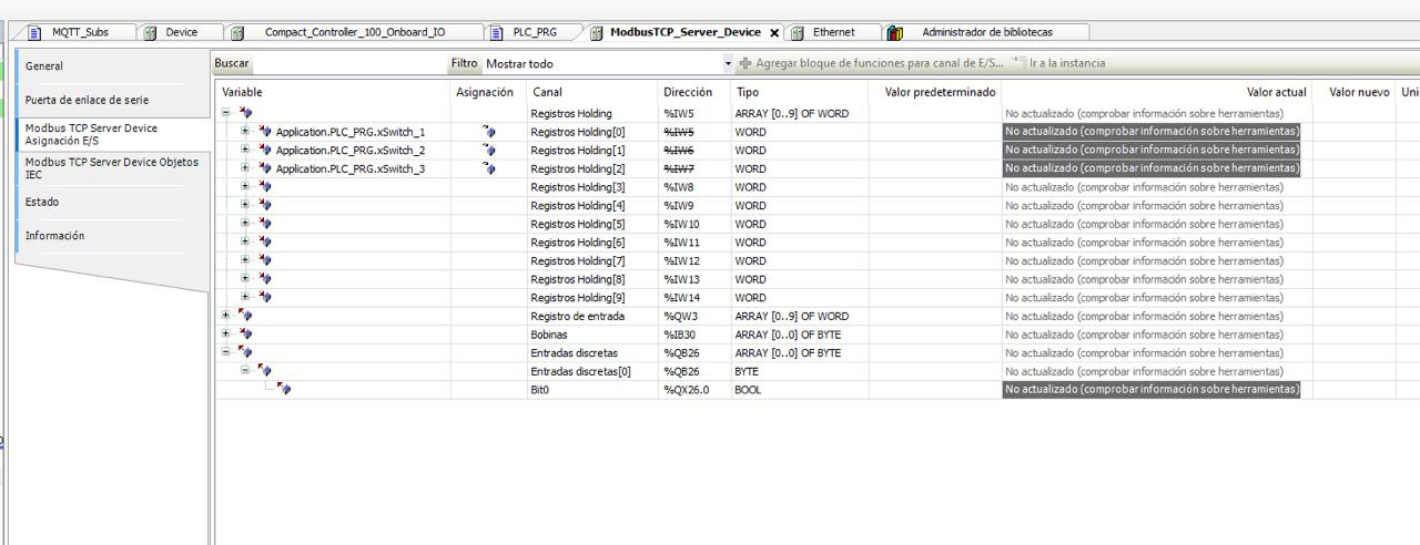
I’ve checked and there is no answer in holding or input (always “0”), only in discrete inputs it is answering correctly.
I checked it by QModMaster, all registers have always “0”, only on discrete input on that address wago is answering with “1”.
@dar3k I would be extremely thankful if you could share your configuration. I also got Wago PLC and I failed some time ago with connecting it using Modbus with HA. I spend a lot of time on it and I couldn’t implement it. I went with Network Variables, NodeRED and HA but that is not a perfect solution. I got communication working on both ways but the NodeRED with the number of entities I needed to put there is a bottleneck.
There are 2 lights, by short click only 1 is going to be on, long press is starting up both, then next short is switching off both, and from HA I have two buttons for controling them.
Code is not needed, I got everything working fine. I’m using a lot of object-oriented programing. For example, I’m not using directly any class from OSCAT or Wago libraries. I got everything wrapped in my own classes and I’ve introduced a Room class. Room class has lights and blinds. So there is a lot of inheritance and interfaces.
I’m more interested in:
KORYTARZ_VIS AT %MX73.0 : BOOL;
KORYTARZ_VIS_2 AT %MX74.0 : BOOL;
As far as I can see you are using 544 and 545 registers. %MX73.0 and %MX74.0 is a reference to those registers? I was not using this notation before.
I think that my problem was that I used the wrong registers. What kind of registers are you using to send data to HA and what to revive data from HA?
On first post you can find a table where you have register numbers. Some of them you can only read. If you would like to write something to PLC you should use registers from 12288.
12288 = %MX0
Physical output you can only read (I verify from it to show current state of output), for physical input in theory you are able to overwrie state by modbus but you shouldn’t do it. So to write something you shall always use NOVRAM registers.
You can define few types of variables: V_BOOL AT %MX0.0 : BOOL; V_BYTE AT %MB0 : BYTE; V_WORD AT %MW0 : WORD; V_DWORD AT %MD0 : DWORD; V_STRING AT %MD0 : STRING(4);
Bit	     %MX11.0 ... 15	 %MX12.0 ... 15
Byte 	 %MB22	  %MB23	 %MB24	%MB25
Word 	 %MW11	  %MW12
BOOL variables should be addressed with the number of the Word and the bit number after a dot.
BYTE variables are addressed by assigning consecutive bytes: %MB22, %MB23 etc.
WORD variables receive the consecutive number of ‘words’ : %MW11, %MW12…
Furthermore, the address itself is built of 4 parts, which we can call „ABCD”:
If your PLC program is not extreamly big you can use %MXx.0 as I did, then from HA side you don’t have to calculate which bit it is and so only sending 1 or 0 but If you have extreamly big PLC program then you should keep it smaller by using less NOVRAM by using %MXx.0 … 15 but then from HA side you need to calculate which number are you sending (much more work).
Hello, Would it be possible to see how you mapp the modbus registry in codesys. I am having a hard time trying to configure that. I just want to send a couple of real values from wago cc100 to home assistant.
I hope you can share some info!
thank you
hello, thank you for your reply. Im kind of lost in mapping between modbus register and Home assistant. Here I assign 3 variables to the registers but I cannot modify them from home assistant. I would greatly appreciate any info you could share. Thank you
In my case to make it simple one variable = one register this is from programming point of view not a good because it lose a lot of memory, your way is correct but need a bit different approach in HA (this is the reason why I used simple approach).
When you make a variables as WORD - so one register = 16 bits with 16 variables you have to make it a bit different on HA side then.
Read WORD for example something like that:
modbus:
  - name: plchub
    type: tcp
    host: IP_ADDRESS
    port: 502
    sensors:
      - name: “PLC WORD”
        address: 100
        input_type: holding
        data_type: uint16
        scan_interval: 1
        # slave: 1 # Optional if you are using Slave ID
and then split this WORD by template to single sensors something like:
template:
  - binary_sensor:
      # Sensor for Bit 0 (e.g., Switch 1)
      - name: “Switch Bit 0”
        state_class: None
        device_class: switch
        # Check if Bit 0 is set (AND with 1)
        value_template: >
          {{ is_state(‘sensor.rejestr_statusu_plc’, ‘unavailable’) or ((states(‘sensor.rejestr_statusu_plc’) | int) & 1) > 0 }}

      # Sensor for Bit 1 (e.g., Switch 2)
      - name: “Switch Bit 1”
        state_class: None
        device_class: switch
        # Check if Bit 1 is set (AND with 2)
        value_template: >
          {{ is_state(‘sensor.rejestr_statusu_plc’, ‘unavailable’) or ((states(‘sensor.rejestr_statusu_plc’) | int) & 2) > 0 }}

      # Sensor for Bit 2 (e.g., Switch 3)
      - name: “Switch Bit 2”
        state_class: None
        device_class: switch
        # Check if Bit 2 is set (AND with 4)
        value_template: >
          {{ is_state(‘sensor.rejestr_statusu_plc’, ‘unavailable’) or ((states(‘sensor.rejestr_statusu_plc’) | int) & 4) > 0 }}
So my way is losing a lot of space in memory of PLC (but my code there is simple and works with that well), but then in HA one register = one sensor, your way required less memory alocation on PLC side but more work on HA side (not as CPU time use but as time spent for configuration).
PS; Try with AI - give it the finall register map and ask for HA confiuration to make for you…