Water level sensor QDY30A modbus RS485 with ESP32 S2 mini

I have bought water level sensor QDY30A from Ali QDY30A - the modbus RS485 version. I am trying to read its values using Wemos ESP32 S2 mini with Esphome and Max485, but no luck. Looks like the modbus connection is completely dead. Sensor docs are not so good, only wiring on that Ali page (and those colors are not correct as I have green instead of black). Some datasheet I found here (PDF). Modbus data sequence written in logs seems to be ok.

What I have also tried with no result:

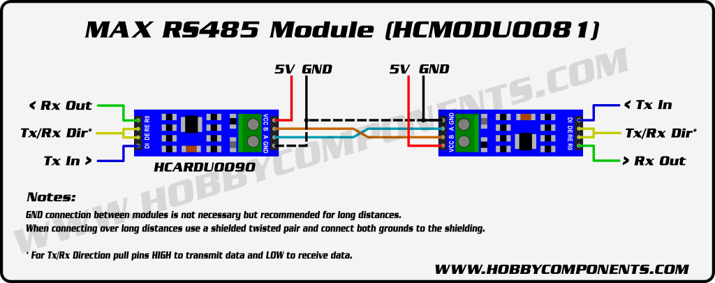
  • connect DE and RE pins on MAX485 and put them to GND (signalizing always ā€œreadā€)
  • switch RX and TX on ESP32
  • switch blue and yellow from sensor (A to B) as some docs shows them switched

Any hints what is wrong?

My wiring:

My yaml

substitutions:
  devicename: water-tank
  friendly_name: Water tank sensor
  device_description:  Water tank sensor (Carat 4m3)

esphome:
  name: ${devicename}
  friendly_name: ${friendly_name}
  comment: ${device_description}

esp32:
  board: lolin_s2_mini #Pinout: https://www.wemos.cc/en/latest/s2/s2_mini.html
  variant: esp32s2
  framework:
    type: arduino

wifi:
  networks:
  - ssid: !secret wifi_ssid
    password: !secret wifi_password
  # Enable fallback hotspot (captive portal) in case wifi connection fails
  ap:
    ssid: ${friendly_name} Hotspot
    password: !secret wifi_ap_password

ota:
  password: !secret ota_password

# Enable logging
logger: 
  level: VERBOSE
  baud_rate: 0

captive_portal:

# restart 
button:
  - platform: restart
    name: Restart

sensor:
# Reports how long the device has been powered (in minutes)
  - platform: uptime
    name: Uptime
    filters:
      - lambda: return x / 60.0;
    unit_of_measurement: minutes

# water level sensor
# https://esphome.io/components/sensor/modbus_controller.html
  - platform: modbus_controller
    modbus_controller_id: qd
    name: "Water level"
    id: modbus_water_level
    register_type: holding
    address: 0x0004
    unit_of_measurement: "cm"
    value_type: S_WORD

# Reports the WiFi signal strength
  - platform: wifi_signal
    name: Wifi Signal
    update_interval: 60s

text_sensor:
  - platform: version
    name: ESPHome Version
  - platform: wifi_info
    ip_address: # exposes the IP Address when connected
      internal: true
      id: wifi_ip_addr
      name: "IP Address"

uart:
  id: mod_bus
  tx_pin: GPIO39
  rx_pin: GPIO37
  baud_rate: 9600
  data_bits: 8
  stop_bits: 1
  parity: NONE
  debug: 

modbus:
  id: modbus1
  uart_id: mod_bus
  send_wait_time: 500ms

modbus_controller:
  - id: qd
    address: 0x01
    modbus_id: modbus1
    setup_priority: -10
    update_interval: 5s

status_led:
  pin:
    number: GPIO15

Logs:

INFO Successfully connected to water-tank @ 172.16.1.243 in 0.347s
INFO Successful handshake with water-tank @ 172.16.1.243 in 8.833s
[19:28:14][I][app:102]: ESPHome version 2024.2.1 compiled on Mar  3 2024, 17:39:55
[19:28:14][C][status_led:019]: Status LED:
[19:28:14][C][status_led:020]:   Pin: GPIO15
[19:28:16][C][wifi:577]: WiFi:
[19:28:16][C][wifi:409]:   Local MAC: 80:65:99:49:8A:98
[19:28:16][C][wifi:414]:   SSID: 'Vega'
[19:28:16][C][wifi:415]:   IP Address: 172.16.1.243
[19:28:16][C][wifi:417]:   BSSID: 2A:3B:82:4D:2D:6C
[19:28:16][C][wifi:418]:   Hostname: 'water-tank'
[19:28:16][C][wifi:420]:   Signal strength: -50 dB ā–‚ā–„ā–†ā–ˆ
[19:28:16][V][wifi:422]:   Priority: 0.0
[19:28:16][C][wifi:424]:   Channel: 9
[19:28:16][C][wifi:425]:   Subnet: 255.255.255.0
[19:28:16][C][wifi:426]:   Gateway: 172.16.1.1
[19:28:16][C][wifi:427]:   DNS1: 192.168.1.1
[19:28:16][C][wifi:428]:   DNS2: 0.0.0.0
[19:28:16][C][logger:447]: Logger:
[19:28:16][C][version.text_sensor:021]: Version Text Sensor 'ESPHome Version'
[19:28:16][C][mdns:115]: mDNS:
[19:28:16][C][mdns:116]:   Hostname: water-tank
[19:28:16][V][modbus_controller:047]: Sending next modbus command to device 1 register 0x04 count 1
[19:28:16][V][modbus:199]: Modbus write: 01.03.00.04.00.01.C5.CB (8)
[19:28:16][V][modbus_controller:509]: Command sent 3 0x4 1
[19:28:16][D][uart_debug:114]: >>> 01:03:00:04:00:01:C5:CB
[19:28:16][V][modbus_controller:047]: Sending next modbus command to device 1 register 0x04 count 1
[19:28:16][V][modbus:199]: Modbus write: 01.03.00.04.00.01.C5.CB (8)
[19:28:16][V][modbus_controller:509]: Command sent 3 0x4 1
[19:28:16][D][uart_debug:114]: >>> 01:03:00:04:00:01:C5:CB
[19:28:17][V][modbus_controller:047]: Sending next modbus command to device 1 register 0x04 count 1
[19:28:17][V][modbus:199]: Modbus write: 01.03.00.04.00.01.C5.CB (8)
[19:28:17][V][modbus_controller:509]: Command sent 3 0x4 1
[19:28:17][D][uart_debug:114]: >>> 01:03:00:04:00:01:C5:CB
[19:28:17][D][modbus_controller:043]: Modbus command to device=1 register=0x04 countdown=0 no response received - removed from send queue
[19:28:20][V][modbus_controller:181]: Updating modbus component
[19:28:20][V][modbus_controller:148]: Range : 4 Size: 1 (3) skip: 0
[19:28:20][V][modbus_controller:047]: Sending next modbus command to device 1 register 0x04 count 1
[19:28:20][V][modbus:199]: Modbus write: 01.03.00.04.00.01.C5.CB (8)
[19:28:20][V][modbus_controller:509]: Command sent 3 0x4 1
[19:28:20][D][uart_debug:114]: >>> 01:03:00:04:00:01:C5:CB
[19:28:21][V][modbus_controller:047]: Sending next modbus command to device 1 register 0x04 count 1
[19:28:21][V][modbus:199]: Modbus write: 01.03.00.04.00.01.C5.CB (8)
[19:28:21][V][modbus_controller:509]: Command sent 3 0x4 1
[19:28:21][D][uart_debug:114]: >>> 01:03:00:04:00:01:C5:CB
[19:28:21][V][modbus_controller:047]: Sending next modbus command to device 1 register 0x04 count 1
[19:28:21][V][modbus:199]: Modbus write: 01.03.00.04.00.01.C5.CB (8)
[19:28:21][V][modbus_controller:509]: Command sent 3 0x4 1
[19:28:21][D][uart_debug:114]: >>> 01:03:00:04:00:01:C5:CB
[19:28:21][V][modbus_controller:047]: Sending next modbus command to device 1 register 0x04 count 1
[19:28:21][V][modbus:199]: Modbus write: 01.03.00.04.00.01.C5.CB (8)
[19:28:21][V][modbus_controller:509]: Command sent 3 0x4 1
[19:28:21][D][uart_debug:114]: >>> 01:03:00:04:00:01:C5:CB
[19:28:22][V][modbus_controller:047]: Sending next modbus command to device 1 register 0x04 count 1
[19:28:22][V][modbus:199]: Modbus write: 01.03.00.04.00.01.C5.CB (8)
[19:28:22][V][modbus_controller:509]: Command sent 3 0x4 1
[19:28:22][D][uart_debug:114]: >>> 01:03:00:04:00:01:C5:CB
...
2 Likes

Not sure, but looks You to connect DE/RE pins together and to ESP board.

See here:

  • flow_control_pin (Optional, Pin): The pin used to switch flow control. This is useful for RS485 transceivers that do not have automatic flow control switching, like the common MAX485.
1 Like

I have tried to connect them together. I did not connect them to ESP board as I am not planning to write to sensor, I am only reading. So I connected them to GND as recommended here:

If you’re only ever going to be either transmitting or receiving then you could tie both DE and RE high (permanent transmit) or both low (permanent receive).

But no data came from sensor.

I made a water level sensor a couple years back has worked flawlessly I used this sensor https://www.amazon.com/gp/product/B087N3LV1J/ref=ppx_yo_dt_b_search_asin_title?ie=UTF8&psc=1 with a D1 mini, the only strange thing is I had to use 12v and 5v power supplies.

esphome:
  name: pond-height
  friendly_name: pond-height

esp8266:
  board: d1

sensor:
  - platform: adc
    pin: A0
    name: "Pond Height"
    update_interval: 36000s
    filters:
      - multiply: 3.3

# Enable logging
logger:

# Enable Home Assistant API
api:
  encryption:
    key: ""

ota:
  password: "

wifi:
  ssid: !secret wifi_ssid
  password: !secret wifi_password

  # Enable fallback hotspot (captive portal) in case wifi connection fails
  ap:
    ssid: "Pond-Height Fallback Hotspot"
    password: ""

captive_portal:

Looks similar, but you have version which returns values as current, I have a modbus RS485 version.

Not a big expert in RS485, but this looks like ESP sending something.
Suggest to connect DE/RE to ESP and configure as descrobed.
Why not.

You were right with a flow control pin. I definitely need to write something to sensor - commands for reading. So I need a flow control pin for MAX485.

Finally my wiring:

I have also switched the A and B (blue and yellow) wires from sensor to MAX485. Now it is working. Sensor is sending unit ā€œcmā€, but is measuring in ā€œmmā€. Measurements are very quick and very accurate (water level in the bucket 122mm, value returned: 122). Current draw by sensor is stable 5.7mA.

My final esphome yaml for those, who will look for working setup in a future:

substitutions:
  devicename: water-tank
  friendly_name: Water tank sensor
  device_description:  Water tank sensor (Carat 4m3)

esphome:
  name: ${devicename}
  friendly_name: ${friendly_name}
  comment: ${device_description}

esp32:
  board: lolin_s2_mini #Pinout: https://www.wemos.cc/en/latest/s2/s2_mini.html
  variant: esp32s2
  framework:
    type: arduino

wifi:
  networks:
  - ssid: !secret wifi_ssid
    password: !secret wifi_password
  # Enable fallback hotspot (captive portal) in case wifi connection fails
  ap:
    ssid: ${friendly_name} Hotspot
    password: !secret wifi_ap_password

ota:
  password: !secret ota_password

# Enable logging
logger: 
  level: DEBUG
  baud_rate: 0

captive_portal:

# restart 
button:
  - platform: restart
    name: Restart

sensor:
# Reports how long the device has been powered (in minutes)
  - platform: uptime
    name: Uptime
    filters:
      - lambda: return x / 60.0;
    unit_of_measurement: minutes

# water level sensor
# https://esphome.io/components/sensor/modbus_controller.html
  - platform: modbus_controller
    modbus_controller_id: qd
    name: "Water level"
    id: modbus_water_level
    register_type: holding
    address: 0x0004
    unit_of_measurement: "mm"
    value_type: S_WORD

# Reports the WiFi signal strength
  - platform: wifi_signal
    name: Wifi Signal
    update_interval: 60s

text_sensor:
  - platform: version
    name: ESPHome Version
  - platform: wifi_info
    ip_address: # exposes the IP Address when connected
      internal: true
      id: wifi_ip_addr
      name: "IP Address"

uart:
  id: mod_bus
  tx_pin: GPIO39
  rx_pin: GPIO37
  baud_rate: 9600
  data_bits: 8
  stop_bits: 1
  parity: NONE
  #debug: 

modbus:
  id: modbus1
  uart_id: mod_bus
  flow_control_pin: GPIO35

modbus_controller:
  - id: qd
    address: 0x01
    modbus_id: modbus1
    setup_priority: -10
    update_interval: 5s

status_led:
  pin:
    number: GPIO15

Thanks a lot to all!

2 Likes

Hello Martin, did you try to change the modbus address of this sensor via esphome ? I want to use two sensors hence the need to change the default modbus address but all my tries failed! Any clue? Thanks

Function 6

Read pdf in first post

hi again, i tried it as following:

  • platform: modbus_controller
    modbus_controller_id: mbtank
    name: ā€œwater tan address changeā€
    id: tan_address_change
    custom_command: [ 0x1, 0x06, 0x00, 0x00, 0x00, 002, 0x0B, 0xE0]
    value_type: S_WORD

and got this error:
[23:26:45][D][modbus:119]: Modbus error function code: 0x86 exception: 1
[23:26:45][E][modbus_controller:091]: Modbus error function code: 0x6 exception: 1
[23:26:45][E][modbus_controller:100]: Modbus error - last command: function code=0x6 register address = 0xCCAD registers count=1 payload size=8

hi again, i tried it as following:

  • platform: modbus_controller
    modbus_controller_id: mbtank
    name: ā€œwater tan address changeā€
    id: tan_address_change
    custom_command: [ 0x01, 0x06, 0x00, 0x00, 0x00, 0x02, 0x0B, 0xE0]
    value_type: S_WORD

and got this error:
[23:26:45][D][modbus:119]: Modbus error function code: 0x86 exception: 1
[23:26:45][E][modbus_controller:091]: Modbus error function code: 0x6 exception: 1
[23:26:45][E][modbus_controller:100]: Modbus error - last command: function code=0x6 register address = 0xCCAD registers count=1 payload size=8
[/quote]

  • platform: modbus_controller
    modbus_controller_id: mbtank
    name: ā€œwater tan address changeā€
    id: tan_address_change
    custom_command: [ 0x01, 0x06, 0x00, 0x00, 0x00, 0x02]
    value_type: U_WORD

Thanks Martin ! I got mine running, but needed to swap ESP32 TX and RX wires in respect to your wiring diagram.
(also See: Modbus with EW11 + QDY30A RS485 water level measure probe - #5 by murcielago)

For your information: my experiments show that the holding register at 0x0005 (zero point) actually is writable. The value will be added to the result in register 0x0004.

BTW: Other registers are also writable and stored, but don’t change anything (unit of measurement, scaling factor)

Hi murcielago,
with your crucial tip to swap TX and RX wires, it also worked for me. Many thanks for that!
I read in another post of yours that you still want to change the millimeters to liters. Did you succeed?
Regards, Frank

Hi, I’m trying to get this sensor working but no luck :frowning:
I have the sensor documentation here and from what I can see I’m doing everything right but I’m not getting any readings.

This is my wiring diagram:

This is my code:

sensor:
# Reports how long the device has been powered (in minutes)
  - platform: uptime
    name: Uptime
    filters:
      - lambda: return x / 60.0;
    unit_of_measurement: minutes
  - platform: uptime
    id: uptime_s
    name: $device_name - Uptime
  # WiFi Signal sensor.
  - platform: wifi_signal
    id: wifi_signal_db
    name: $device_name - WiFi Signal
    update_interval: 10s
  - platform: copy # Reports the WiFi signal strength in %
    source_id: wifi_signal_db
    name: "$device_name - WiFi Signal Percent"
    filters:
      - lambda: return min(max(2 * (x + 100.0), 0.0), 100.0);
    unit_of_measurement: "%"
    entity_category: "diagnostic"

# water level sensor
# https://esphome.io/components/sensor/modbus_controller.html
  - platform: modbus_controller
    modbus_controller_id: qd
    name: "Water level"
    id: modbus_water_level
    custom_command: [ 0x01, 0x03, 0x00, 0x04, 0x00, 0x01, 0xC5, 0xCB]
    unit_of_measurement: "cm"
    value_type: S_WORD
  - platform: modbus_controller
    modbus_controller_id: qd
    name: ā€œwater tan address changeā€
    id: tan_address_change
    custom_command: [ 0x01, 0x03, 0x00, 0x04, 0x00, 0x01, 0xC5, 0xCB]
    value_type: U_WORD
# Reports the WiFi signal strength
  - platform: wifi_signal
    name: Wifi Signal
    update_interval: 60s

text_sensor:
  - platform: version
    name: ESPHome Version
  - platform: wifi_info
    ip_address: # exposes the IP Address when connected
      internal: true
      id: wifi_ip_addr
      name: "IP Address"
  - platform: version
    name: $device_name - ESPHome Version
  # Expose WiFi information as sensors.
  - platform: wifi_info
    ip_address:
      name: $device_name - IP
      update_interval: 10s
    ssid:
      name: $device_name - SSID
      update_interval: 10s
    bssid:
      name: $device_name - BSSID
      update_interval: 10s
  - platform: template
    name: $device_name - uptime
    lambda: |-
      uint32_t dur = id(uptime_s).state;
      int dys = 0;
      int hrs = 0;
      int mnts = 0;
      if (dur > 86399) {
        dys = trunc(dur / 86400);
        dur = dur - (dys * 86400);
      }
      if (dur > 3599) {
        hrs = trunc(dur / 3600);
        dur = dur - (hrs * 3600);
      }
      if (dur > 59) {
        mnts = trunc(dur / 60);
        dur = dur - (mnts * 60);
      }
      char buffer[17];
      sprintf(buffer, "%ud %02uh %02um %02us", dys, hrs, mnts, dur);
      return {buffer};
    icon: mdi:clock-start


uart:
  id: mod_bus
  tx_pin: GPIO17
  rx_pin: GPIO18
  baud_rate: 9600
  data_bits: 8
  stop_bits: 1
  parity: NONE
  debug: 

modbus:
  id: modbus1
  uart_id: mod_bus
  send_wait_time: 500ms

modbus_controller:
  - id: qd
    address: 0x01
    modbus_id: modbus1
    setup_priority: -10
    update_interval: 5s

Any ideas?

Also interested in doing this, but I have the QDY30A from Aliexpress but have the 0-10V version which just has red (+), green (-) and a yellow wire. I’m unsure how to wire this up to the ESP32, any ideas? I realise I can only get 5V max on the pins, so what else can be used to get the right resolution here?

Connect tx to tx on your hw519 to the esp and rx to rx, Not crossed! Than it worked on my project
In your wiring you us 16 and 17 thats korrect!
Your code is 17 and 18!

Exactly, that RS485 converter is translator, not the the device that actually communicates through serial.

Hope this helps to anybody GitHub - lejmr/dyi-ha-water-management: Water level management