So, I have two underground oblate toroid (think elongated doughnut) water tanks, joined together making a total of 10,000 litres. This is used to water our garden beds and lawn. I wanted to be able to monitor the amount of water in the tanks, and (as it doesn’t have a float switch) switch the pump off in the event that the water level is getting low - to both protect the pump from burning out should it try to run without water, as well as to stop the pump from dredging up the last few litres that can contain silt that will in turn clog up the watering system.
There are many options out there do do this. I did find a number of people have used sensors that measure the distance to the top of the water which is fine, but can have issues with reflections and you also have to be careful to use something that is protected against water ingress. I instead decided to try a fuel/water sensor as they are rugged sealed stainless steel sensors (used in boats, caravans and cars), and are simple and reliable. Another alternative for me would have been a pressure sensor resting on the bottom of the tank, but I was a little concerned about the cabling etc being constantly submerged plus the math required to work out volume in an oblate toroid made me go ‘meh’. Cost of the sensors were similar, so I went the fuel/water sender (available on Aliexpress, Amazon etc as well as many auto and marine stores - I got mine via eBay).
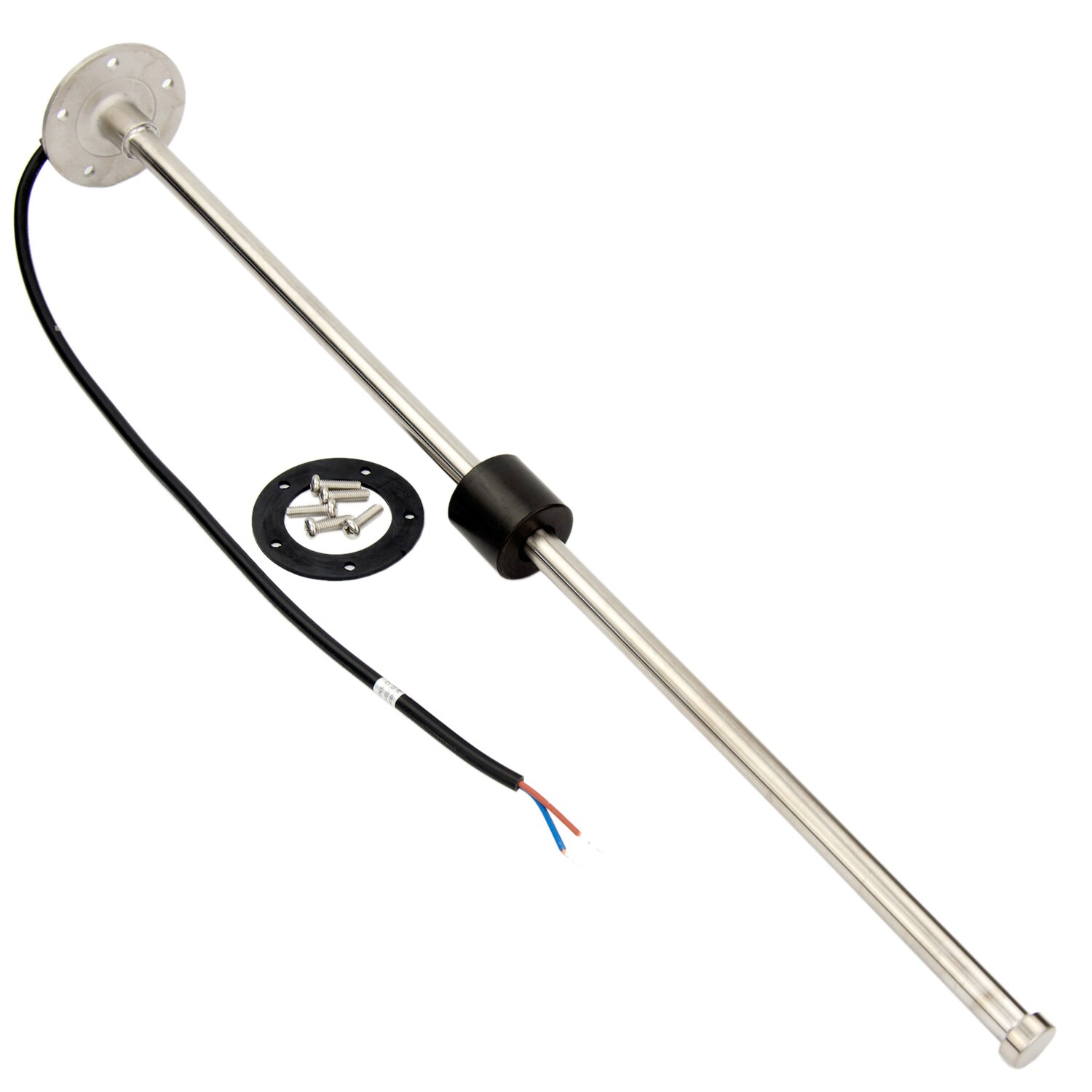
Getting it to work was actually pretty simple. Hardware required:
- Fuel/water sensor
- Wemos D1 mini
- Pullup resistor to keep the voltage below 1V (the limit for A0 on the D1) - in my case I needed a 1.8k resistor. I had some 2k resistors, so used one of those.
- Small hobby box
- Usb cable & charger
- Cable (I used irrigation cable as it can cope with being buried in the ground etc)
I installed the sensor in the tank, joined the cable from the sensor to the irrigation cable (either solder and heat shrink the joins, or use gel filled crimp connectors - also frequently available in the irrigation section of hardware stores eg https://www.bunnings.com.au/k-rain-idc-gel-cable-connectors-5-pack_p0242399), then ran the cable to where I was going to keep the D1 mini.
I connected my D1 to my hassio server, and uploaded my esphome code on to it, then made sure I could update it wirelessly. Then I hooked everything up. With my sensor there were two wires - one black and one blue. I doubt it matters which wire is used for what, but I ran the black one to ground on the D1 mini. As this was a test, I used a small breadboard - later I’ll probably solder everything up for reliability. Anyhow, the blue wire I ran to a spare row on the breadboard. Then from that row I ran a wire to A0. From that row I also connected my 2k resistor to a second row, then from that row I connected a wire to 3V on the D1.
Initially I set the sensor to take readings every second. Then using the log option in esphome I made a note of the voltage readings as I moved the float up the sensor rod - I decided that 5cm increments would be good enough. I could then use math along with info from my tank supplier to work out what voltages would show specific percentage levels based on height. I then changed the readings to be done every 30 seconds.
If you try to replicate this, the voltage levels & associated percentage levels, plus the pullup resistor will almost certainly be different. See also Monitoring Water Level from Vanomation who did something very similar and I did borrow some of his code! To calculate the pullup resistor you require, multiply the maximum ohm rating of your sensor by 9, then get a resistor that is larger than that. My sensor has a range of 0-190 ohm, so rough calc is 190*9=1710 ohm. So I needed something bigger than 1.71k ohm. 2k was fine.
esphome sensor code:
sensor:
  - platform: uptime
    name: "watersens01 Uptime"
  - platform: wifi_signal
    name: "watersens01 WiFi Signal"
    update_interval: 60s
  - platform: adc
    pin: A0
    name: "Water Level Voltage"
    id: water_voltage
    update_interval: 30s
    accuracy_decimals: 3
    filters:
      - multiply: 3.3
  - platform: template
    name: "Water Level Percent"
    unit_of_measurement: "%"
    accuracy_decimals: 0
    update_interval: 30s
    lambda: |-
      if (id(water_voltage).state < 0.02578) {
       return 25;
      } else if (id(water_voltage).state < 0.05479) {
       return 30;
      } else if (id(water_voltage).state < 0.06768) {
       return 33;
      } else if (id(water_voltage).state < 0.09023) {
       return 35;
      } else if (id(water_voltage).state < 0.10957) {
       return 40;
      } else if (id(water_voltage).state < 0.12246) {
       return 45;
      } else if (id(water_voltage).state < 0.13213) {
       return 50;
      } else if (id(water_voltage).state < 0.15469) {
       return 53;
      } else if (id(water_voltage).state < 0.16113) {
       return 56;
      } else if (id(water_voltage).state < 0.18047) {
       return 60;
      } else if (id(water_voltage).state < 0.19336) {
       return 64;
      } else if (id(water_voltage).state < 0.19980) {
       return 67;
      } else if (id(water_voltage).state < 0.21592) {
       return 71;
      } else if (id(water_voltage).state < 0.23848) {
       return 75;
      } else if (id(water_voltage).state < 0.25137) {
       return 85;
      } else {
       return 100;
      }
You could also create a “volume” to show the total number of litres available, although in my case I didn’t bother as it’s a 10,000 litre tank so it’s pretty easy to work out what is there - if it’s 75% then it’s 7,500 litres!

