Greetings, I am building a water system for my farmhouse
I am looking for some help as can’t code to save my life but am a descent plumber and electrician
Scope: Use esp12f_relay_30A x4 board to control a deep well pump that fills a cistern.
Use a water meter with pulser, as flow / no flow sensor aka well dry shut lockout with 1hr cool
Use a float switch as tank full sensor
How: use a water meter pulser connected to IO as flow sensor and report pulse to HA for usage
use a float switch as demand no demand sensor/tank full lockout, connected to IO
set up some type of scheduling, via an hourly duty cycle, IE 25% = 15 min ON 45 min OFF
Do all this onboard of the esp automation running on esp chip.
Bonus able to set cool down, duly cycle,  shutdown lockout mode, from esp webpage
          able to turn on a vacation mode or override shutdown via HA
          send an alert, or turn on a light if, float switch registers demand for 12+ hrs ( tank is not filling)
          send an alert, or turn on a light if, if no flow on the meter after 2 consecutive  well dry cool-downs
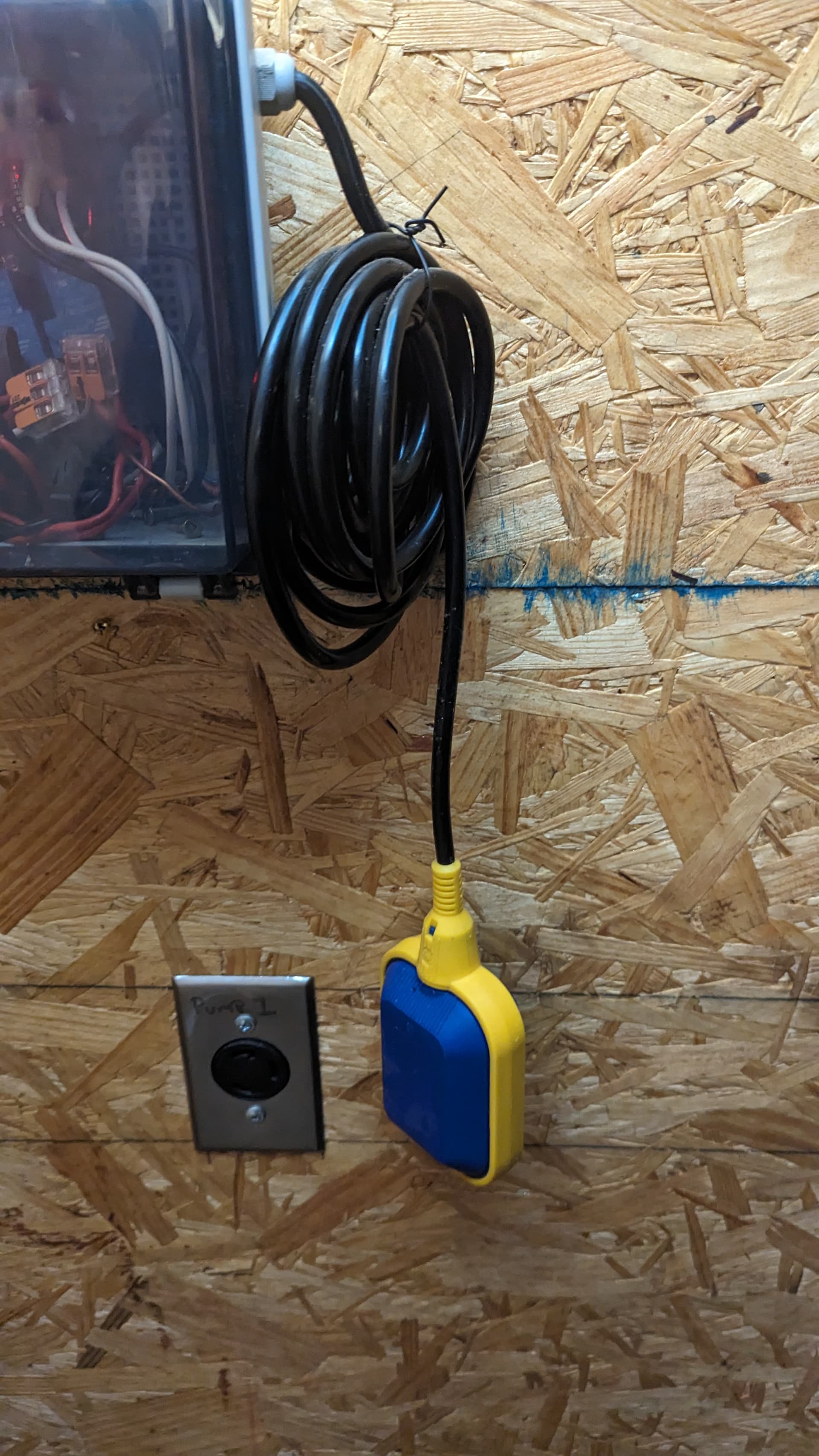
hardware esp12f_relay_30A x4 board , Water Meter with Pulse Output Pulse = 1 Gallon , float switch
with NO + NC contacts
At this point, I have all the hardware and can turn the pump on and off via the webpage and HA.
The board is set up for 1 IO per relay, However, my pumps are 2 phases (240V-USA) so the 4 relays will be divided into pairs and give 1 IO for each set. relay pair 2 will be for a pressure pump switch only and is out of scope for this part.
The idea would be a duty cycle schedule would run, ie 25% =15 min per hr, Top of Hour run, next it would check the float valve, if contact is Closed, engage relay pair 1 , monitor float switch if contact opens disengaged relays, monitor water meter pulser if no pulse for 40 seconds, disengage relays.
documentation
relay
float switch
https://www.amazon.com/gp/product/B07K4BYFSW/ref=ppx_yo_dt_b_search_asin_title?ie=UTF8&psc=1
watermeter
Pictures


just have a base config at this point that runs the relays, Where should I begin, do you think it’s possible to do this and have it run on the esp Chip?
web_server:
  port: 80

status_led:
  pin:
    number: GPIO5
    inverted: True

switch:
  - platform: gpio
    pin: GPIO16
    name: Relay1
    id: relay1
  - platform: gpio
    pin: GPIO14
    name: Relay2