Hello Everyone,
I am installing a esphome setup for the ground floor. I want to controll a banner light, motor, outside light and a corridor light. I have a standard relay module used with arduino.
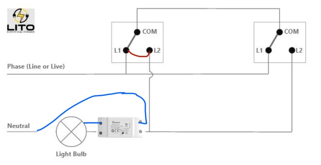
The problem I am facing is the corridor light is hook up with a 2 way switch like this:
I want to add relay switch on top of the existing wiring, i want to retain the functionalities of existing switches. Also I only have access of one of the switch because of the loaction of esp8266 and relay modules. Can this be done without removing one switch and replacing it with relay.
That is going to be difficult. Your existing wiring is the strangest 3-way switch connections that I have ever seen. And I’ve seen some weird ones. (In the US, this is called 3-way. Everywhere else it’s 2-way). In order for the original switches to work you have to get access to both switches and do some rewiring.
this is indeed the strangest way of a 2 way switch circuit, but it works tho.
if you can replace 1 switch with a intermediate switch and insert a 2 way relais into the mix, it’s doable, but you’ll need to rewire to the “normal” standard.
you’ll need to rewire like drawing below.
1st switch some wires to switch around, second switch replace with intermediate one and add relay behind the new switch.
The Wiring is embeded in the home so not possible to rewire it. I maybe able to remove one switch and replace it with a relay. Is there a way to do it non destructively?
there is no need to rewire the embeded wiring in the wall, only in the switches you have to change the wires to another connection of the switch.
you’ll have only one wire left going to the light that you won’t need anymore.
Thanks for the different solutions.
The problem I have is that I can’t access the other switch and light fixture because of there position from the esp8266 that controlls all the ground floor. so the solution provided by @Krivatri Might be something i need to look into. I was hopeing to not add or remove anything and just add the relay in parallel just like we do for normal switches.
2gang switching is kinda challanging in home automation and keeping physical buttons functional and there are lots of different soluitons provided by different products
For what’s worth: I solved it with a shelly 1pm mini. But looking at your schema, it kinda depends how that phase line is running between the switches as it would need to be like this to work:
If he can’t access both switches to rewire them, your solution won’t work. Your “schematic” depicts the traveler wires typical of 3-way switches (2-way in EU). If he would rewire both switched to a conventional 3-way (2-way) switch, then a solution would be much more straightforward.
I was an electrician in a prior life (long retired now) and I’ve never heard of a “phase line”. Is this a European term?
I was going to impliment solution found here all throught the stair case up to 5th floor and integrate them with motion sensors. All of them have 3 - way switches (2-way in EU). One floor has 2 switches, for the staircase one above and one below. Removing and rewiring means doing it for the whole appartment. so if there is a solutioon that I could add on top with the help of a relay (That I already bought quite a few) and esp8266 that would be ideal.
@Krivatri’s 3-way wiring is the technically correct answer.
I had a similar situation and went for something simpler with a small compromise: I connected my switches to Shelly i4s which then directly trigger the Shelly 1 at the light over WiFi. The compromise is that you need a network, but it’s simple in the sense that the only wiring you need is to connect a button to a Shelly i4 input, and to wire the Shelly 1 relay to the light. This also works independent of HA (but you can totally route the switch events via HA if you wanted to). This might be useful to you. In my case the other 3 inputs of each Shelly i4 have buttons on them too to do other things (control more relays, or to set scenes).
Nitpick, but it’s 2-way switching. 2-gang or 2-lever refers to the number or switches on a plate. In this case we’re talking about 3-way switching.
No one said anything about removing anything. Your first schematic" shows two switches and now you have three? As I said, your 2/3-way wiring is very unconventional. You can do this with a smart switch but you have to rewire both switches to conventional 2/3-way configuration. You might be able to do it with the existing wiring using two smart wall switches and one smart device like the shelly at the light.
Please explain why not?
I also am an electrician, this is a basic schematic for 3 or more light switches in series, in Europe anyways.
Only the drawing of the intermediate switch is technically wrong, but did it like this to simplify things, it doesn’t represent the inner workings of the switch.
also I took into consideration that he wants to retain the functionalities of the existing switches and access to only 1 switch to add the relay or wires coming from the relay.
therefore this should be the best solution for this case I guess?