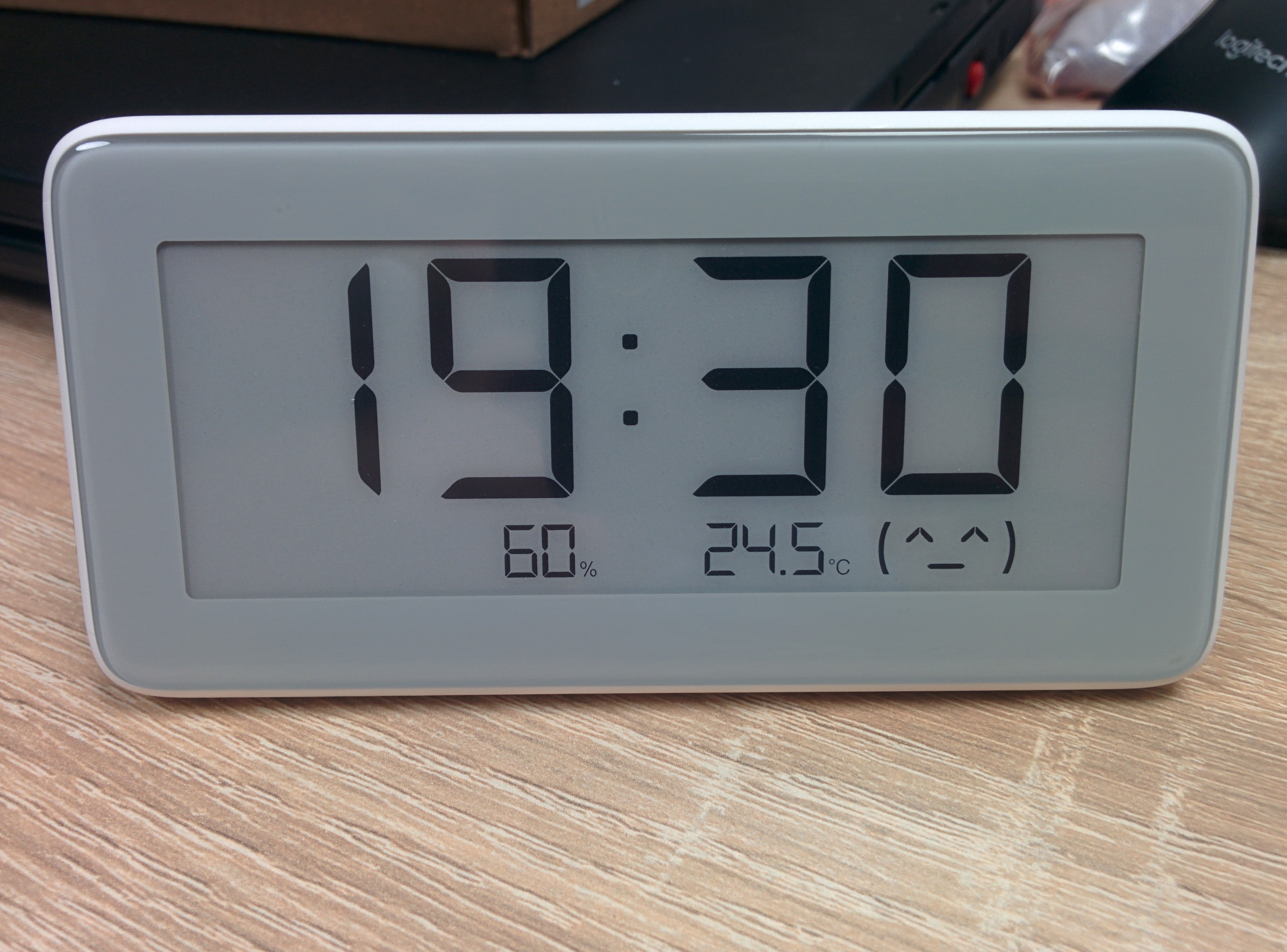
Hi, I just want to share one bit unusual and maybe bit unrelated project here. Don’t have account over on another forum but still want to post it somewhere. I have Xiaomi E-ink clock LYWSD02. They have Bluetooth and I read temperature and humidity using ESPhome (so it is bit related  ). But there is no other way how to set time other than the official Xiaomi app - which is TERRIBLE. It won’t even automatically adjust for DST change! Not really “smart” clock…
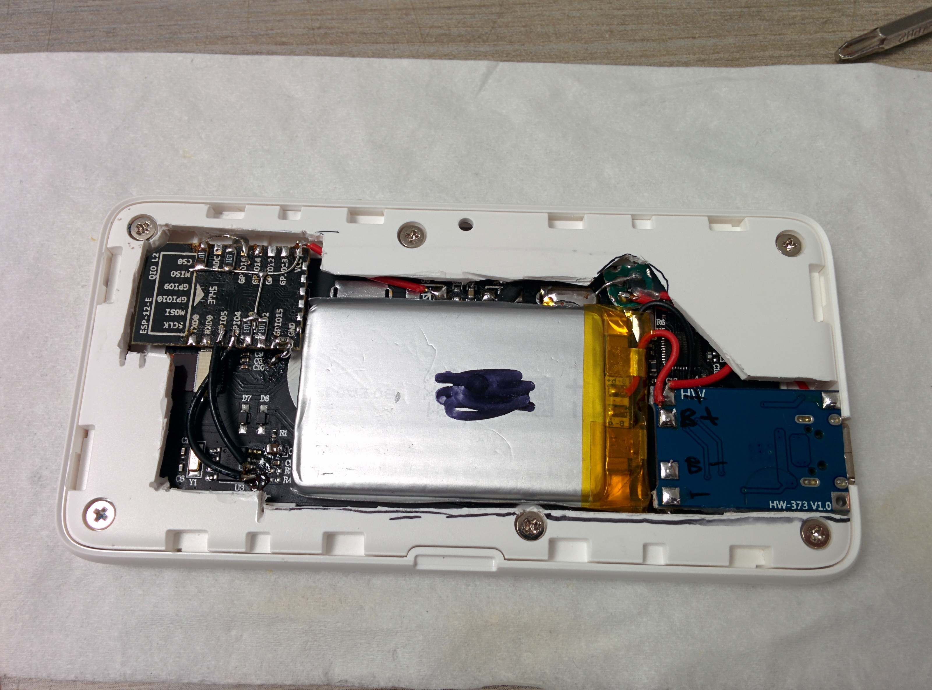
When I opened the clock I found that the RTC IC used if PCF8563 that has libraries available for Arduino! So I decided to add ESP8266 INSIDE that pulls precise time using Wi-Fi from NTP server and sets the RTC of the clock.
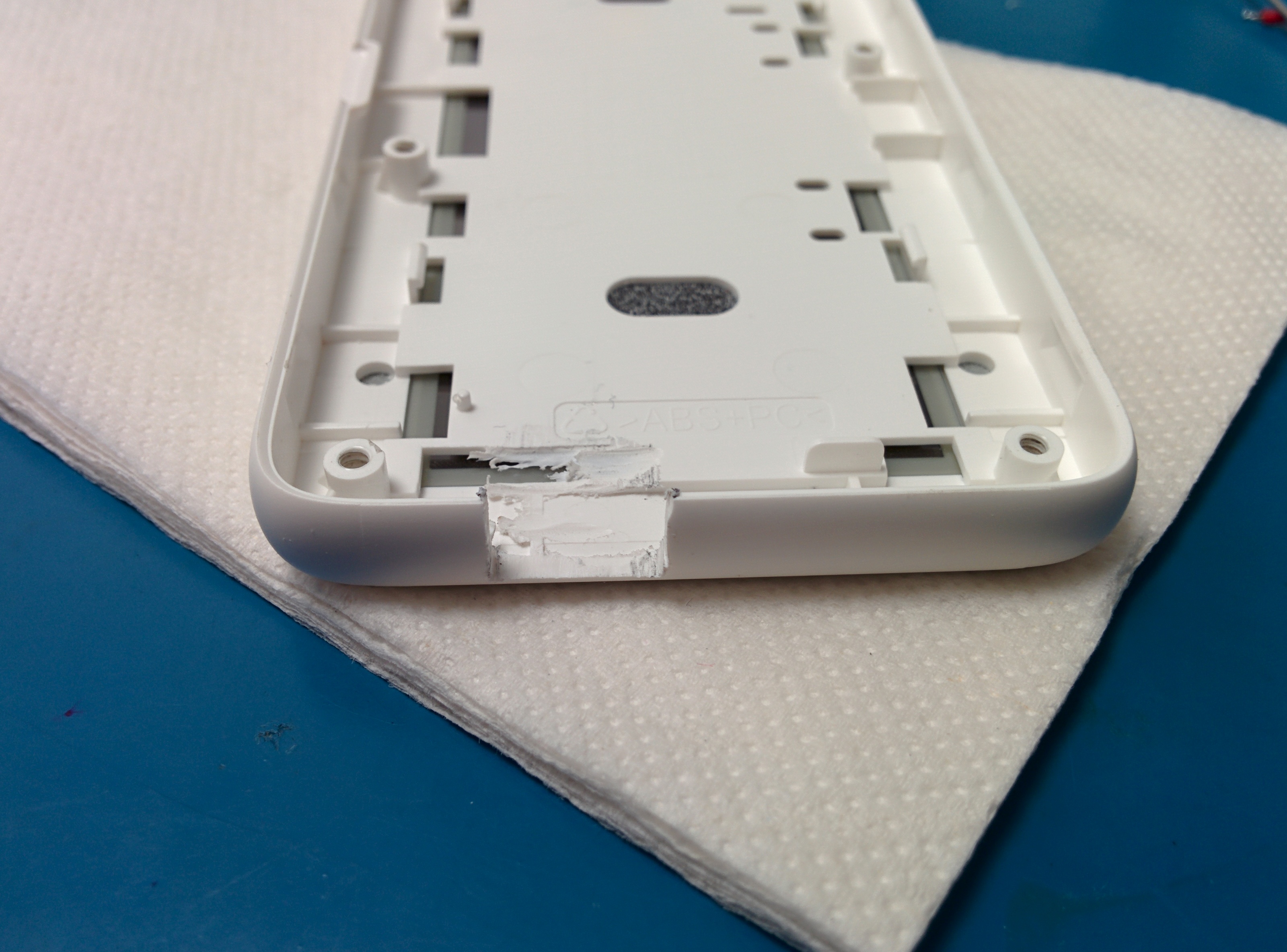
Here you can enjoy teardown pictures of the clock:

While I was at it I changed the power supply because:
- I frickin hate manufacturers for using CR2032 or other small coin cell batteries for regular devices like this.
- the ESP8266 draws quite a lot of current while transmitting (around 80mA) and I don’t know if those CR2032s will reliably deliver this current without any voltage sags
- It fells wasteful to use such small non-rechargeable cells for this purpose anyway
I first disconnected display and got the original PCB out of the plastic frame.

Then I desoldered and cleaned battery 1,2 and 3 holders and D8 and D9 diodes. Btw battery 3 is small (probably intended as) not user-replaceable CR1220 that keeps the internal RTC running while you change the main batteries so the clock won’t require synchronization after battery change.

I looked inside the clock to the PCB and laid down all components (esp, charger…) I will need to add and then started to search for the right sized battery. Found one manufacturer on Aliexpress with wide variety of li-polymer batteries. He even had the store sorted by thickness of the cells! Great. I measured that 4mm thickness is ideal and found some 600mAh (~500mAh real) 48x30mm battery.
Ok great, we have battery, now we need to charge the battery - for that purpose I used those cheap boards with TP4056. I choose the version with USB type C port - looks better than microUSB  By default those boards charge at 1A which is too fast for 500mAh battery. Charging current is easily changed by replacing single resistor (look into datasheet for TP4056). I replaced it with 4k7 which gives around 270mA charging current.
For the USB port I used dremel with cutting disc and some files to make hole in the main frame

Ok now we have battery, charger for the battery but we need to adjust the voltage bit. The original CR2032 have voltage range from roughly 3.2V fully charged down to 2.5V discharged. But the Li-polymer we have has range from 4.2V fully charged to 3V discharged. Those 4.2V will blow the microprocessor as its maximum voltage is only 3.6V And the ESP8266 we want to add is also 3.6V maximum. So we need voltage regulator (LDO). I selected MCP1700T-3302E as it has really small quiescent current (few uA) and sufficient current capability (250mA). I squeezed the LDO in the place where D9 was so its output connects to the 3V line that runs through the PCB.

Input is connected to the pad where the original battery was so it gives me big pad to solder battery wire. For ground I scratched the soldermask on the ground area that is almost everywhere. Now we need the ESP. I had some ESP-12-E in my parts bin so I don’t know the exact origin but it works fine. We just need to add some resistors as the ESP needs certain pins low or high during startup. We need to pull high (using 10k resistor) following pins:GPIO0, GPIO2, RESET, EN(CH-PD). And pull down GPIO15. We also need to connect GPIO16 to the RESET pin so the wakeup from deep sleep works. And of course don’t forget to connect VCC to 3V line and GND to ground (again I made myself a pad by scratching the soldermask on the ground plane).For the communications with RTC I just connected SCL and SDA to the RTC. I know that having another master on I2C bus is not exactly “proper technique” but well…who cares, it works…The probability that there will be collisions is really small.
I didn’t bother with making custom PCB (and there is not much space (thickness) anyway so I just soldered resistors and wires directly on top (bottom) of the ESP.
I also implemented simple P-MOSFET switch that disconnects power while it is charging (Gate is connected to USB +5V, drain goes to clock and source goes from battery positive).
I intended this as reset in case something gets stuck or ends in weird state when for example the battery discharges and the protection circuit will act strange during threshold voltage while charging. So if you plug the USB, power to the clock and ESP is disconnected. When you disconnect it will reenergize again. I would say this is optional and causes some issues like when you unplug the power is shows wrong time (As the RTC goes dead as its capacitor discharges in few minutes) so you have to let it synchronize and either wait like 30minutes or plug and unplug the power again. Alternatively you could route the power to the RTC separately and let it be always on and disconnect only the rest of the clock+ESP. Didn’t bother with that though
Then it was necessary to cut big parts if the inside plastic part that norally covers the whole PCB
As the last step I smoothed the back cover in the place where it originally pressed down those CR2032 batteries. Every fraction of milimeter counts!

SOFTWARE PART:
For the RTC communication I used this library: https://github.com/orbitalair/Rtc_Pcf8563
And for the NTP and time processing I modified the example I found here:
Article: https://www.arduinoslovakia.eu/blog/2017/7/esp8266---ntp-klient-a-letny-cas?lang=en
Code on GitHub: https://github.com/RoboUlbricht/arduinoslovakia/tree/master/esp8266/ntp_client
I just removed the code that prints the time onto the serial terminal and used it to set RTC instead
rtc.setDate(day(t), weekday(t), month(t), 1, ((year(t))%2000));
rtc.setTime (hour(t), minute(t), second(t));
Then I tweaked the code (set SSID, password, NTP server, move the code into setup as the deep sleep makes “loop ()” useless etc.
First I just wanted to use something like ESP.deepSleep(86400e6); This means the ESP will wake only once a day (86400seconds=24hours), connect to Wi-Fi, load time from NTP, update the time in RTC and go to sleep again for the day. But I found out that maximum sleep time is determined by uint32 max size. Which is 4294967295uS=71minutes. That sucks, as it is way too often to sync every hour or so. So I needed a workaround. We will still wake up every let’s say hour but still sync only every 24hours. For this I used RAM memory that keeps the data even during deep sleep. And I just used one integer as counter if we ran desired number (24) of 1 hour cycles.
The memory will survive deep sleep and resets but won’t survive without power. So when you first power the ESP it will read some garbage as the counter number. It really does not matter as I just test every run if the absolute value of the counter is smaller than 24. So it does not matter if it reads 25 as regular sync-run or it reads 45875 as garbage on cold boot – either way it will synchronize the time and store “1” to the counter. Yes if by any chance the garbage read as 5 for example, it won’t synchronize the time right now but I think I can live with it
Known issues:
The RTC stores date and time in UTC. The local offset is synchronized from the mobile app. So while I was at GMT+1 AND had summer time and I reset the clock it will show 02:00. Later now in “winter” time (or when you manually change time zone in your phone) it changes the offset in the microcontroller (that we can’t access). This means after reset it shows 01:00. This means that if you tweak your ESP to give correct time during one season and later open official app and let it sync, the next time the ESP synchronizes the time it will be 1 hour off! Not an issue for me as I don’t use the app at all.
Also the microcontroller in the clock reads time from RTC only every 30minutes give or take. This means if you perform cold boot the clock will quickly read and display some old/garbage time on the display (as the ESP needs few seconds to connect to wifi and update the RTC). It will correct itself in 30minutes or after you quickly plug/unplug the USB lead – the RTC has capacitor and will survive few minutes. Yeah I know, I stole the RTC battery as I described in hardware mod section I added 10uF capacitor to the unpopulated pads next to the RTC - manufacturer was probably thinking about having capacitor there but later decided not to.
The WiFi SSID and password is hardcoded - so it will require reflash in the event of SSID/password change. Maybe later I could implement some wifi manager that starts configuration AP+HTTP server in the event of cold boot (after USB disconnect like I stated previously) when connection to configured AP fails. But I didn’t want to complicate the project right now.
Battery charger: https://www.aliexpress.com/item/33038674816.html
Battery: https://www.aliexpress.com/item/32784827079.html
Final result - looks great if you ask me


Here is the arduino code. Didn’t have time to polish it so it looks awful, I know…
/**
   Arduino ESP8266 UDP NTP Client
   v. 1.1
   Copyright (C) 2017 Robert Ulbricht
   http://www.arduinoslovakia.eu

   Get the time from a Network Time Protocol (NTP) time server.
   Convert time to few localtimes.

   IDE: 1.8.2 or higher
   Board: NodeMCU 0.9 (ESP-12)

   Libraries:
   TimeLib: https://github.com/PaulStoffregen/Time
   Version: 1.5 or higher
   Timezone: https://github.com/JChristensen/Timezone
   Version: 1.0 or higher

   This program is free software: you can redistribute it and/or modify
   it under the terms of the GNU General Public License as published by
   the Free Software Foundation, either version 3 of the License, or
   (at your option) any later version.

   This program is distributed in the hope that it will be useful,
   but WITHOUT ANY WARRANTY; without even the implied warranty of
   MERCHANTABILITY or FITNESS FOR A PARTICULAR PURPOSE.  See the
   GNU General Public License for more details.

   You should have received a copy of the GNU General Public License
   along with this program.  If not, see <http://www.gnu.org/licenses/>.
*/
struct {
  int counter;
} rtcData;


#include <ESP8266WiFi.h>
#include <WiFiUdp.h>
#include <TimeLib.h>
#include <Timezone.h>
#include <Rtc_Pcf8563.h>

char ssid[] = "xxx";  //  your network SSID (name)
char pass[] = "xxx";       // your network password


unsigned int localPort = 2390;      // local port to listen for UDP packets

IPAddress timeServerIP; // time.nist.gov NTP server address
const char* ntpServerName = "192.168.40.1";

const int NTP_PACKET_SIZE = 48; // NTP time stamp is in the first 48 bytes of the message

byte packetBuffer[ NTP_PACKET_SIZE]; //buffer to hold incoming and outgoing packets

// A UDP instance to let us send and receive packets over UDP
WiFiUDP udp;

//Central European Time (Frankfurt, Paris)
TimeChangeRule CEST = {"CEST", Last, Sun, Mar, 2, 0};     //Central European Summer Time 120 je offset leto, 60offset zima
TimeChangeRule CET = {"CET", Last, Sun, Oct, 3, -60};       //Central European Standard Time
Timezone CE(CEST, CET);

Rtc_Pcf8563 rtc;


void setup()
{

  Serial.begin(115200);
  delay(100);

// RTC memory Read
  if (ESP.rtcUserMemoryRead(0, (uint32_t*) &rtcData, sizeof(rtcData))) {
  }

if (abs(rtcData.counter)>24) {
  rtcData.counter=1;


  WiFi.softAPdisconnect(true);
  Serial.println();

  // We start by connecting to a WiFi network
  Serial.print("Connecting to ");
  Serial.println(ssid);
  WiFi.begin(ssid, pass);
   byte wifiCNT = 0;
 while (WiFi.status() != WL_CONNECTED && wifiCNT < 23) {
    delay(500);
    Serial.print(".");
    wifiCNT++;
  }
  Serial.println("");
  Serial.println("IP address: ");
  Serial.println(WiFi.localIP());

  Serial.println("Starting UDP");
  udp.begin(localPort);
  Serial.print("Local port: ");
  Serial.println(udp.localPort());


time_core();
}


rtcData.counter= rtcData.counter + 1;
 Serial.println(" ");
 Serial.print("counter");
 Serial.println(rtcData.counter);

  //RTC memory Write
if (ESP.rtcUserMemoryWrite(0, (uint32_t*) &rtcData, sizeof(rtcData))) {
  }

  ESP.deepSleep(3600e6);


}

void loop ()
{
  }

void time_core()
{
  //DNS preklad addr->IP
  WiFi.hostByName(ntpServerName, timeServerIP);

  sendNTPpacket(timeServerIP); // send an NTP packet to a time server
  // wait to see if a reply is available
  delay(1000);

  int cb = udp.parsePacket();
  if (!cb) {
    Serial.println("no packet yet");
  }
  else {
    Serial.print("packet received, length=");
    Serial.println(cb);
    // We've received a packet, read the data from it
    udp.read(packetBuffer, NTP_PACKET_SIZE); // read the packet into the buffer

    //the timestamp starts at byte 40 of the received packet and is four bytes,
    // or two words, long. First, esxtract the two words:

    unsigned long highWord = word(packetBuffer[40], packetBuffer[41]);
    unsigned long lowWord = word(packetBuffer[42], packetBuffer[43]);
    // combine the four bytes (two words) into a long integer
    // this is NTP time (seconds since Jan 1 1900):
    unsigned long secsSince1900 = highWord << 16 | lowWord;
    Serial.print("Seconds since Jan 1 1900 = " );
    Serial.println(secsSince1900);

    // now convert NTP time into everyday time:
    Serial.print("Unix time = ");
    // Unix time starts on Jan 1 1970. In seconds, that's 2208988800:
    const unsigned long seventyYears = 2208988800UL;
    // subtract seventy years:
    unsigned long epoch = secsSince1900 - seventyYears;
    // print Unix time:
    Serial.println(epoch);

    TimeChangeRule *tcr;
    time_t utc;
    utc = epoch;
    rtc.initClock();


 //   printTime(utc, "UTC", "Universal Coordinated Time");
 //   printTime(CE.toLocal(utc, &tcr), tcr -> abbrev, "CZE");
    nastavRTC(CE.toLocal(utc, &tcr), tcr -> abbrev, "CZE");
 //   readRTC ();


    Serial.println("");

  }
  // wait ten seconds before asking for the time again
 // delay(10000);
}

// send an NTP request to the time server at the given address
unsigned long sendNTPpacket(IPAddress& address)
{
  Serial.println("sending NTP packet...");
  // set all bytes in the buffer to 0
  memset(packetBuffer, 0, NTP_PACKET_SIZE);
  // Initialize values needed to form NTP request
  // (see URL above for details on the packets)
  packetBuffer[0] = 0b11100011;   // LI, Version, Mode
  packetBuffer[1] = 0;     // Stratum, or type of clock
  packetBuffer[2] = 6;     // Polling Interval
  packetBuffer[3] = 0xEC;  // Peer Clock Precision
  // 8 bytes of zero for Root Delay & Root Dispersion
  packetBuffer[12]  = 49;
  packetBuffer[13]  = 0x4E;
  packetBuffer[14]  = 49;
  packetBuffer[15]  = 52;

  // all NTP fields have been given values, now
  // you can send a packet requesting a timestamp:
  udp.beginPacket(address, 123); //NTP requests are to port 123
  udp.write(packetBuffer, NTP_PACKET_SIZE);
  udp.endPacket();
}


void printTime(time_t t, char *tz, char *loc)
{
  sPrintI00(hour(t));
  sPrintDigits(minute(t));
  sPrintDigits(second(t));
  Serial.print(' ');
  Serial.print(weekday(t));
  Serial.print(' ');
  sPrintI00(day(t));
  Serial.print(' ');
  Serial.print(month(t));
  Serial.print(' ');
  Serial.print(year(t));
  Serial.print(' ');
  Serial.print(tz);
  Serial.print(' ');
  Serial.print(loc);
  Serial.println();
}


void nastavRTC(time_t t, char *tz, char *loc)
{

  rtc.setDate(day(t), weekday(t), month(t), 1, ((year(t))%2000));
  rtc.setTime (hour(t), minute(t), second(t));
  Serial.print ("RTC SET");
}

void readRTC()
{
  Serial.print("Hour:");
  Serial.println(rtc.getHour());
  Serial.print("Minute:");
  Serial.println(rtc.getMinute());
  Serial.print("Second:");
  Serial.println(rtc.getSecond());
  Serial.print("Weekday:");
  Serial.println(rtc.getWeekday());
  Serial.print("Day:");
  Serial.println(rtc.getDay());
  Serial.print("Month:");
  Serial.println(rtc.getMonth());
  Serial.print("Year:");
  Serial.println(rtc.getYear());
  }

//Print an integer in "00" format (with leading zero).
//Input value assumed to be between 0 and 99.
void sPrintI00(int val)
{
  if (val < 10) Serial.print('0');
  Serial.print(val, DEC);
  return;
}

//Print an integer in ":00" format (with leading zero).
//Input value assumed to be between 0 and 99.
void sPrintDigits(int val)
{
  Serial.print(':');
  if (val < 10) Serial.print('0');
  Serial.print(val, DEC);
}
