@sts I am powering it from a usb outlet behind the wall using one of these Excel and Linea Dual USB Charger Mechanism - AU Site that I had wired into a light switch that sits on the wall behind the aircon control panel also using it to power a wall mounted tabled as well just running the USB cables through the wall so they are hidden.
You %100 could achieve that setup with some automations just in HA which I personally I think would be easier to mange rather than trying to do it with the esp-home firmware.
You could get away with doing those automations without needing the climate entity as well as it only really depends on your temperature sensors and pressing the respective zone/room buttons when your temperatures are reached.
Hey All,
I’ve been following along with this and trying to get it working myself and this is my first post. Just putting mine together now. Does the SENS pin on J1 connect to anything? Also, does the A0 connect anywhere either? I’m not sure i’m reading the diagram right but they seem to not lead anywhere? I think i’m getting close…
Apart from that I have put my circuit together as per the diagram, but using a multimeter I seem to be getting voltages in the mV range when measuring between Key and Com on J1 at any DAC value…
Any help would be greatly appreciated!
No, as far as I understand SENS (sensor) wire comes from the external thermistor sensor if you have it (indirectly from the hub). We don’t need it here.
As far as I can tell I replicated @lordvorta 's set up. Same controller, DAC and the schematics (veroboard a couple of posts above).
Triple checked everything - all seems ‘according to specs’. Flashed the ESPhome, connected to Home Assistant, all great from that side, logs are alive, connected to the panel - it does nothing?
How do you debug this thing? I connected it to desk power station at 5V on signal wire, do I also need 19v on the power wire?
It seems to me we only use it to read the LEDs (and I obviously cant send LED sequences manually).
Anyway, when connected to psu at 5v nothing happens when I press any buttons.
What do I do now? If it was off by some I could re-calibrate it in the code but it just seems to be totally fine and basically dead at the same time so what do I do?
I connected it to desk power station at 5V on signal wire, do I also need 19v on the power wire?
I’m not sure what “power” wire you mean or which “signal” wire you connected to 5V.
You need to provide your ESP32 board with external 5VDC (usually via USB connector, but can also be to 5V supply pins), it does not get power from the Actron unit. If you look at my schematic from 6 Jan the 5V from the ESP32 also needs to supply the DAC. The only connections to the Actron unit are via the 3 lines shown in my diagram.
Blockquote
It seems to me we only use it to read the LEDs (and I obviously cant send LED sequences manually).
Anyway, when connected to psu at 5v nothing happens when I press any buttons.
The circuit senses the voltage on the “Power” line from actron which actually contains pulses which the ESP decodes via input G33 to get the status of the LEDs on the panel. The DAC simulates key presses by changing the voltage on the “KEY” line.
Blockquote
What do I do now? If it was off by some I could re-calibrate it in the code but it just seems to be totally fine and basically dead at the same time so what do I do?
The veroboard diagram you posted a while ago is not very easy to interpret as you have no labels on it. I would have to both guess what you have connected to the incoming lines and then lookup the pinouts of the chips you have in your circuit. If you fully label your diagrams, I can easily compare them with what I have and offer assistance.
Also make sure you are supplying your ESP32 with an external 5V supply which you do not show on your diagram
Thanks for getting back to me, mate, I really appreciate it.
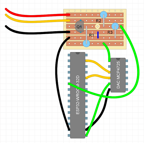
I used the same components as @lordvorta , and I used the labels from the schematics you posted a bit ago, namely:
1 x esp32-wroom-32
1 x DAC MCP4725
1 x BC548 NPN Transistor (Q1)
1 x 20k Resistor (R1)
1 x 4.7k Resistor (R2)
1 x 1.2k Resistor (R3)
On the schematics below (repost) ‘external’ wires come from the AC wall panel and respectively are:
RED - POWER (19V)
YELLOW - KEY (4.95V)
BLACK - ground
The blue connection between D and E tracks is a short.
Q1 bottom leg (vero D3) is Emitter.
Note the cut-out at C6.
DAC orientation is OUT at the ‘top’, GND at the ‘bottom’ (see photos)
ESP connections are:
D32 - vero C10
GND - vero E1
D22 - DAC SCL
D21 - DAC SDA
GND - DAC GND
3V3 - DAC VCC
DAC connections (other than above): OUT - F7 (I ended up putting it on F1 but that should make no difference).
It might look on the photo like there is a short between ESP GND and 3V3 but it’s not - this is just the angle of the photo.
The testing setup is simple:
ESP powered on.
External power supply connected to ‘GND’ and ‘KEY’ inputs to the vero supplying 4.95V. The red input wire - ‘POWER’ is not connected (since I have no ability to simulate pulses I figured it’s not essential at this stage).
ESP starts and connects to HA, although I prefer to use the local web-server at this point.
Everything on the ESP side looks normal, as far as I can tell - I can see the logs from ESP on every button press.
The problem is the voltage on the output never changes.
UPD: now that I’m looking closer at it, it seems my transistor is reverted (both on schematics and the board)? I’d appreciate if you could verify this.
For testing, it sounds like you don’t have it connected to the keypad, is that correct?
Do not connect an external supply to the KEY line, you cannot simulate it that way. All you can test is the output from the DAC, then connect it to the real keypad.
Hey mate, how’d you go once flipping the transistor? I think i’m at the same stage as you, i’m still prototyping on a breadboard, but i might put the veroboard together too. Will let you know if I make any progress.
Thanks all for the amazing work on this.
I’ve been giving it a go the last day or so and have it running now
I originally also had the transistor the wrong way around but it works once I flipped that.
Now that core functionality is working I’ve been doing a bit of work on the esphome code that might be of use to others.
To simplify things I pulled out the button press stuff to it’s own ‘function’ (which is implemented as a template button called ‘Press’
To use it I set a global value to the desired DAC setting, and then call id(press_button).press()
Using this I’ve also turned the room buttons (and power button) into switches so they show up nicely.
I’ve also exposed the fan speed as a number based on sensor states.
Hopefully this will be helpful to someone else.
The DAC I’m using supports 3.3v and 5v - so have it plugged into 5v (seemed a smidge more stable at that voltage)
BTW - to figure out the values I sat there with a multimeter (set to report DC voltage connected) to the keypad (gnd+key) and pressed each button one-by-one - noting down the reported value.
Next I connected to the multimeter to my circuit (which was not connected to keypad) at the points where the cable would go to the keypad.
Then I sat there changing the “DAC Output milliVolts” until I got the values to match what I recorded as closely as possible.
Those were the values then that I plugged into the esphome yaml
Great work getting that all working @cjd - looks really good.
Sorry I’m still a bit stuck - I think i’m really close to getting it working but have a few questions.
1 - I measured the voltage directly out of the MCP4725 in my circuit and can see 0-5v with my multimeter as i change the dac milivolts input in ESP Home.
However, with my circuit disconnected from the wall controller I do not measure any voltage across the GND and Key lines. The Vout from the MCP4725 goes to the 20k resistor, then into the transistor as per the circuit diagram that @brentk posted above. Looking at the datasheet of the BC548 Transistor posted above it goes into the BASE (pin 2 of the transistor). The collector (pin 1) then goes to the Key Line and the Emitter (pin 3) then goes to ground. Is that correct? Or am i misinterpreting how the transistor is used? Do i have it incorrectly connected there?
Measuring across the ground and key lines i dont see a voltage change but do see a resistance change.
2 - When connecting the circuit to the actual aircon, is it done in parallel similar to the diagram below?
Looks nice!
I noticed you have 2 different versions of ESP code - one with external DAC and one with internal, but both have ADC pin as 33, is that a coincidence?
Did the LED decoding work fine for you?