Anyone had any experience integrating an Aiphone intercom / gate controller ?
I have an older model JK-1MED. I dont know whether you can add an ESP32 or similar. I would like to receive notifications when the intercom button is pressed and maybe to be able to remotely respond.
3 Likes
I would like this too
Outstanding idea! Definitely interested but no knowledge on how to…!
Just upgraded and installed a JO Wireless unit but it is not integrated with HA yet.
It has the same footprint as the JK unit So an easy swap out.
Just bought a house with a J0-1MD screen (not W) and a J0-DV video doorbell. There is but one twisted pair between them for video, sound, doorbell signal and whatnot (+ another pair for door unlocking, but this one is for later). I’d like to put my rpi between the MD and the DV, so that hass can interact with both (receive a/v from doorbell, send a/v to screen, catch button press from doorbell…). Not sure how feasible this all is, I’ll let you know. This would work with the ‘W’ version as well, probably.
3 Likes
@Kernono did you manage to figure out how these connections on the twisted pair work?
I am looking at the JO wireless unit (where the master screen is connected to the home wifi). Has anyone made progress on integrating this setup with HA?
Here’s what I managed to do/figure out:
- I connected a Wemos D1 mini powered from the intercom’s 18V power supply (with a step down)
- I connected to MCU the L+L connectors to be able to open/close the gate and detect when the existing wired gate open/close button is pressed.
- The A1+A2 intercoms wires seem to be carrying an analogue audio/video signal from the video camera panel unit (this is what it looked like in my oscilloscope, peaks shifted from 16V to 3V using a 13V Zener diode).
- It’s possible to detect when the button on the camera unit is pressed (voltage goes form 9V to ~16V), but opening the video feed in the mobile app or the intercom display unit would also have the same effect of increasing the voltage, and I could not figure out how to differentiate this from a button press.

I have a JF-2MED, on the back of my panel there is a breakout for an NTSC signal.
I use the following setup to forward the video to my NVR:
- Raspberry pi 4 (a zero wasn’t fast enough)
- YOTOCAP USB capture card
- volume control attenuator for tapping off the speaker
- ffmpeg for transcoding
The problem is that the video feed is only active if the video is on for the station, otherwise it’s dark. As far as I know there isn’t a way to have it be always on and recording.
Hi there, I’m trying to use the “Doctor call” feature of my AIPHONE GT-1A model which should open the door automatically but I’m not sure if this feature should also be enabled centrally first.
The tenant terminal has an “Option Connector” - by shorting the “DC” terminals, it should enable the automatic entry/ doctor call feature:


After doing the above, I try to follow the following instructions but no luck with that - the automatic entry is not enabled 

Do you have any experience with this feature or any insight to share? I had automated a doorbell before with a ESP 8266 but this doorbell seems trickier and at this point in time I just want to enable this automatic entry/ “doctor call” feature.
Cheers
Did you get the doctor call working? I have the same airphone and im looing to automate a notification and the possibility to open the gate from my HA.
Doctor call would solve some of the issues.
If not, did you end up automating it? Im kinda heading towards tapping into the “open” button and just emulate a button click.
Hi there/ @Asphaug
I ended up automating as the “Doctor Call” feature is centrally managed for the whole condo.
The automation consists on using an ESP32 board with ESPHOME to capture the incoming call signal via the “Blue (-)” and “White (+)” pins from the options connector, then switching on the “Talk” button, then “Door Unlock” button and then the “Talk Button” again to close the speaker and mic session.
A few pointers that may help as I couldnt find anything on the internet to automate this particular doorbell:
-
Energy: I have tried to power the ESP32 from the R1/R2, C1/C2 connectors using buck and line converters from the original 24v to 5V without success as it messes up with the doorbell call i.e. you’ll be able to power up the ESP32 but you wont get the incoming call anymore. This doorbell is TRICKY and very sensitive to current/voltage draws, so two options here:
1.a) use a nearby outlet and 5V converter to your board (if you have an AC line behind the doorbell, it would be ideal)
1.b) use a battery powered board - this is the approach I have chosen with a TTGO T18 with a 18650 battery which should last around 6 months with the deep sleep feature: when an incoming call is captured, the board wakes up, triggers the automation as part of the “on boot” and goes back to sleep. -
The incoming call captured by the white and blue connector has 5V so I have used a potentiometer to convert it to 3V
-
I have soldered some wires to the “Talk” and “Door Unlock” switch contacts - if you dont want to mess around with soldering, you may try using “Conductive Adhesive Glue” - search for that on AliExpress
-
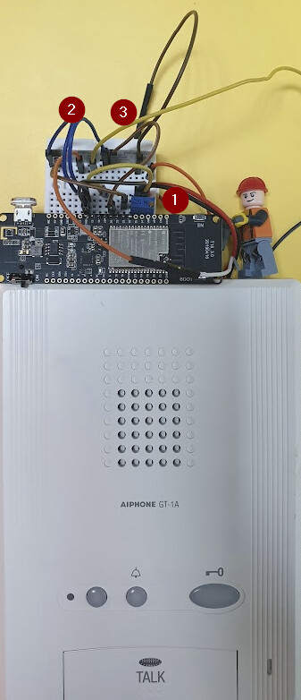
For the switching, I’m using the HF49FD relay in my prototype version shown below - too many wires for now… but it works

4.1: incoming 5V signal converted to 3V
4.2: Talk switch
4.3: Door unlock switch
- When I get more time, I’ll do a smaller version with either the HFD4/3 relay or 2N3904 NPN transistors for the switching, S2 mini board with a battery shield and a smaller battery to minimize the overall size.
Hope it helps with your automation.
Cheers
2 Likes
Thanks for an awsome reply!
I got a good idea of what im gonna do from here. Probably gonna use a ESP8266 with ESPHOME.
I have never used a relay like that, and only the digital blue ones capable of switching 250v. Could you throw together a quick paint scheme of the wiring of just one of those buttons with the relay?
What pin makes the relay click? I understand that the 2 on the left will simulate a “button click”, but how does the right aprt work?

Either way, thanks alot! i allready got what i need to atleast get a notification when a call is recieved, so ill start there.
Hi @Asphaug ,
The traditional blue boxy relays are too bulky for many projects indeed… Reason why I prefer these HF* relays or transistors to do the switching.
The pins on the right you connect to the ESP board pins: a GPIO pin of your choice and the ground pin.
Once the GPIO is activated - in my case when the board wakes up as part of the on_boot sequence, it will execute the “button click”.
Cheers
For those wondering, this is how i made mine:
Pin 3 and 4 in the options connection on the back of my Airphone (Airphone GT-1M3-L) is 24v. I used a couple of resistors to get this down to 3.3 ish volts which the esp8266 NODEMCU can take.
In ESPHOME i just set up a notification if the voltages goes over 2v on analog1, and that works just fine.
For my prototyope i just yanked 2 wires on there, but i will terminate them into a connection later on when i make a PCB and a 3d printed enclosure.

For the door opening part i just solderer 2 wires on the back of the “unlock” button on the airphone.
I just used 220v relay for the prototype, but will probably buy a smaller one like @HoneyBadger100

This is how my horrible prototype ended up looking like (No wires are color coded, because thats how i roll, shit) :

To go more in debt on the software side, this is the esphome setup:
sensor:
  - platform: adc
    pin: A0
    name: "Ringeklokke Analog"
    update_interval: 2s
    filters:
      - multiply: 3.3
switch:
  - platform: gpio
    name: "Ringeklokke lock"
    pin: GPIO5
    id: relay
    inverted: true
    on_turn_on:
    - delay: 500ms
    - switch.turn_off: relay
3 Likes
Hello Mike, has the JO been swapped out on a JK1-MED? Does the app work then?
Hi,
Thanks a lot, I aslo have an Airphone GT-1M3-L that I would like to connect to HA.
I especially need to be able to open the door remotely because I can always hear the ring bell but the intercom is one floor down.
Could you plz give more details on your system and required components, 'looks like this is exactly what I need.
Regards,
amazing work. I have a gt-1m3 as well and would love to get this thing hooked up. By the way, my landlord doesn’t even know how to use it, yet he installs it in every unit he owns. Any tips on getting this thing to actually work? My old apartment allowed me to use it as a peep hole (city boy and there’s a lot of weirdos outside). I have suspicion the dip switches are totally incorrect, as this entire brand new apartment was wired by a couple of hacks. sw1 set to a, dip1 is on the rest are off.

Hi Asphaug!
I have a question about your setup. I recently got the exact same model intercom installed in my building that you have in your pics. First question is about the unlock button…I’m assuming it’s the blue and white cables I see soldered in the pic of the intercom PCB. I tried just shorting those two pads to see if it triggers the same activity as pressing the button but nothing happens. Do you send a voltage through them? Also, is this supposed to just mimic the button press, or is it a direct door unlock function? Thank you so much for all the info!
Are you able to provide a slightly more detailed guide on this?