Alpac Helty Flow VMC - The modbus way

When I bought a new house in 2021, I struggled a lot on how to interface the existing VMC (or MEV – Mechanical Extract Ventilation) to Home Assistant to control and monitor them in a more granular and automated fashion. The house is equipped with five Helty Flow Compact VMC’s by Alpac (Flow40 HRV with wall recess: the Helty concealed ventilation system (heltyair.com)) with no wifi nor remote control.

The only way to control them is via their modbus RS485 RTU interface. The 7 pins onboard connector provides the modbus pins in position 5 (data+) and 4 (data-).

I then decided to build a custom circuit to read available sensors from the VMC and control it remotely via modbus. What is needed:

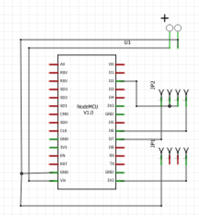
I used 2x 15 pin headers for the NodeMCU and 2x 4 pin header for the modbus converter. I added a two poles terminal block to power the NodeMCU from a 5V power adapter. Circuit diagram is the following:

The as built circuit is the following:
image
image

And here is the final one with NodeMCU and modbus converter:
image

The firmware on the nodemcu must be compiled using Arduino IDE (I used v2.1.0 but any version is OK). You need to adjust the settings with your wifi and MQTT info, change the modbus slave ID if different from the default 2, adjust the name of the ESP device (mine is VMC_Letto in the below example) and eventually change the used MQTT topics.
The first upload of the firmware must be from a wired connection. After the initial deploy, it will support OTA updates by browsing to http:///update.

////////////////////////////////////////////////////////////////////////
//                                                                    //
//    ModBus gateway to Helty VMC via NodeMCU and WIFI/MQTT support   //
//                                                                    //
//    MQTT telemetry:                                                 //
//      vmcs/vmc_sala/state (speed status)                            //
//      vmcs/vmc_sala/info  (json format)                             //
//                    IntTemperature (internal temperature)           //
//                    ExtTemperature (external temperature)           //
//                    Alarm (Alarm flag)                              //
//                                                                    //
//    MQTT Settings telemetry:                                        //
//      vmcs/vmc_sala/teleperiod (MQTT update period)                 //
//                                                                    //
//    MQTT Commands:                                                  //
//      vmcs/vmc_sala/cmnd/teleperiod (MQTT update period)            //
//      vmcs/vmc_sala/cmnd/speed (0 to 7, speed setpoint)             //
//      vmcs/vmc_sala/LWT (Last Will Testament)                       //
//                                                                    //
//    Version History:                                                //
//      1.0 - Initial Tests                                           //
//      2.0 - First working build                                     //
//      3.0 - Moved info to json                                      //
////////////////////////////////////////////////////////////////////////
  
// include libraries
#include <ESP8266WiFi.h>
#include <PubSubClient.h>
#include <stdio.h>
#include <stdlib.h>
#include <ArduinoJson.h>

// required for OTA updates
#include <ESPAsyncTCP.h>
#include <ESPAsyncWebServer.h>
#include <AsyncElegantOTA.h>

// required for modbus communication
#include <ModbusRTU.h>
#include <SoftwareSerial.h>

//
//        CONFIGURATION SECTION
// wi-fi and mqtt connection parameters
//
const char* ssid = "<YOUR WIFI SSID>";        // Enter your WiFi name
const char* password =  "<YOUR WIFI PWD>";    // Enter WiFi password
const char* mqttServer = "<MQTT IP>"; 		// MQTT host IP
const int mqttPort = <MQTT PORT>;             // MQTT TCP port
const char* mqttUser = "<MQTT USER>";         // MQTT username
const char* mqttPassword = "<MQTT PWD>";     	// MQTT password
//
//     END OF CONFIGURATION SECTION
//


// RS485 setup with NodeMCU
#define RE_DE D2  // Connect RE&DE terminal to pin GPIO4
#define RX D6     // pin GPIO12
#define TX D7     // pin GPIO13

#define SLAVE_ID 2        // slave ID
#define REG_COUNT 1       // registries count (does not support multiple readings)
#define SPEED_HREG 1000   // holding register 1000 - speed
#define INTTEMP_IREG 1000 // input register 1000 - internal temperature
#define EXTTEMP_IREG 1001 // input register 1001 - external temperature
#define ALARM_IREG 1006   // input register 1006 - alarm flags

// speeds settings
#define SPEED_ZERO 0x0000   // speed zero
#define SPEED_ONE 0x0001    // speed one
#define SPEED_TWO 0x0002    // speed two
#define SPEED_THREE 0x0003  // speed three
#define SPEED_FOUR 0x0004   // speed four
#define SPEED_HYPER 0x0005  // hyper speed
#define SPEED_NIGHT 0x0006  // night speed
#define SPEED_COOL 0x0007   // free cooling speed

// variables
uint16_t res;
uint16_t value;
String Msg = "";            // message for debug to MQTT
long period = 2000;         // period between two consecutive mqtt updates (msec)
unsigned long time_now = 0; // timestamp for mqtt refresh
int speed = 0;              // speed set
int speedO = 0;             // speed set old value
char buffer [10];
char output [256];

// MQTT topics
const char* TOPIC_LWT =  "vmcs/vmc_letto/LWT";             // last will testament
const char* TOPIC_CMD =  "vmcs/vmc_letto/cmnd/#";          // all commands
const char* TOPIC_CMD1 = "vmcs/vmc_letto/cmnd/teleperiod"; // setup TelePeriod command
const char* TOPIC_CMD2 = "vmcs/vmc_letto/cmnd/speed";      // set speed command

// answers to command
const char* TOPIC_TELE =  "vmcs/vmc_letto/state";          // speed status
const char* TOPIC_TELE1 = "vmcs/vmc_letto/teleperiod";     // MQTT update period
const char* TOPIC_TELE2 = "vmcs/vmc_letto/info";           // info


// initialize libraries for modbus
SoftwareSerial S(RX, TX);
ModbusRTU mb;

// initialize web server for OTA
AsyncWebServer server(80);
// initialize wi-fi client
WiFiClient espClient;
// initialize mqtt client
PubSubClient client(espClient);
// prepare for json encoding
StaticJsonDocument<200> doc;


//
// callback function to monitor modbus communication errors
//
bool cb(Modbus::ResultCode event, uint16_t transactionId, void* data) { 
  if (event != Modbus::EX_SUCCESS) {
      Serial.printf_P("Request result: 0x%02X, Mem: %d\n", event, ESP.getFreeHeap());
  }
  return true;
}

//
// read holding register
// returns the register value
//
uint16_t rdHreg(uint16_t ADDRESS) {
  if (!mb.slave()) {    // Check if no transaction in progress
    digitalWrite(RE_DE, HIGH);
    mb.readHreg(SLAVE_ID, ADDRESS, &res, 1, cb); // Send Read Hreg from Modbus Server
    delayMicroseconds(120);
    digitalWrite(RE_DE,LOW);
    while(mb.slave()) { // Check if transaction is active
      mb.task();
      yield();
    }
    Serial.println(res);
  }
  return res;
}

//
// write holding register
//
void wtHreg(uint16_t ADDRESS, uint16_t VALUE) {
  if (!mb.slave()) {    // Check if no transaction in progress
    digitalWrite(RE_DE, HIGH);
    mb.writeHreg(SLAVE_ID, ADDRESS, VALUE, cb); // Send write Hreg to Modbus Server
    delayMicroseconds(120);
    digitalWrite(RE_DE,LOW);
    while(mb.slave()) { // Check if transaction is active
      mb.task();
      yield();
    }
  }
}

//
// read input register
// returns the register value
//
uint16_t rdIreg(uint16_t ADDRESS) {
  if (!mb.slave()) {    // Check if no transaction in progress
    digitalWrite(RE_DE, HIGH);
    mb.readIreg(SLAVE_ID, ADDRESS, &res, 1, cb); // Send Read Ireg from Modbus Server
    delayMicroseconds(120);
    digitalWrite(RE_DE,LOW);
    while(mb.slave()) { // Check if transaction is active
      mb.task();
      yield();
    }
    Serial.println(res);
  }
  return res;
}


//
// MQTT connection function
//
void mqtt_connect() {
  // Connect to MQTT broker
  if (client.connect("VMC_Letto", mqttUser, mqttPassword,TOPIC_LWT,1,true,"Offline" )) {
    // Connection to MQTT successful
    Serial.println("Connected!");  
    // Subscribe to settings topics
    client.subscribe(TOPIC_CMD);    // subscribe to all command topics
    client.publish(TOPIC_TELE1, itoa((int)period,buffer,10), true); // teleperiod
    client.publish(TOPIC_LWT, "Online");  // last will testament

  }
}

//
// WIFI connection function
//
void wifi_connect() {
  // Connect to WIFI
  if (WiFi.status() != WL_CONNECTED) {
    Serial.println("Connecting to WiFi..");
    WiFi.mode(WIFI_STA);
    WiFi.begin(ssid, password);

    WiFi.setAutoReconnect(true);
    WiFi.persistent(true);
    
  }
}

//
// Callback function for MQTT subscriptions
//
void mqtt_callback(char* topic, byte* payload, unsigned int length) {
 
  String message = (char*)payload;
  String thetopic = (char*)topic;
  message = message.substring(0,length);
  char buffer [5];

  // prepare MQTT message for debug
  Msg = "Message arrived in topic: " + thetopic + " -> " + message;
  Serial.println(Msg);
  
  // decode subscribed messages and return confirmation
  // telegram period
  if (thetopic == TOPIC_CMD1) {
    Serial.print("TelePeriod=");
    period = message.toInt();
    Serial.println(message);
    client.publish(TOPIC_TELE1, itoa(period,buffer,10), true);
  }

  // speed
  if (thetopic == TOPIC_CMD2) {
    Serial.print("Speed=");
    speed = message.toInt();
    Serial.println(message);
  }

  Serial.println();
  Serial.println("-----------------------");
 
}


//
// setup routine
//
void setup() {
  pinMode(RE_DE,OUTPUT);  // direction pin
  Serial.begin(115200);   // start serial port
  S.begin(19200, SWSERIAL_8N1); // setup software serial
  mb.begin(&S); // start software serial
  mb.master();  // start Master modbus processing

  // Connnect to local wifi
  WiFi.mode(WIFI_STA);
  WiFi.begin(ssid, password);
 
  // Wait for wifi connection
  Serial.println("Connecting to WiFi..");
  while (WiFi.status() != WL_CONNECTED) {
    delay(500);
    Serial.print(".");
  }
  Serial.println("");
  Serial.print("Connected to ");
  Serial.println(ssid);
  Serial.print("IP address: ");
  Serial.println(WiFi.localIP());

  WiFi.setAutoReconnect(true);
  WiFi.persistent(true);

  // activate http server for OTA updates
  server.on("/", HTTP_GET, [](AsyncWebServerRequest *request) {
    request->send(200, "text/plain", "Hi! I am VMC Letto.");
  });

  // Start ElegantOTA
  AsyncElegantOTA.begin(&server);
  server.begin();
  Serial.println("HTTP server started");

  // Set MQTT broker
  client.setServer(mqttServer, mqttPort);
  
  // Set the callback function for MQTT subscriptions
  client.setCallback(mqtt_callback);
 
  // Connect to MQTT broker
  Serial.println("Connecting to MQTT...");
  while (!client.connected()) {
    Serial.print(".");
 
    // Attempt connection to MQTT
    if (client.connect("VMC_Letto", mqttUser, mqttPassword,TOPIC_LWT,1,true,"Offline" )) {
      // Connection to MQTT successful
      Serial.println("Connected!");  
      // Subscribe to settings topics
      client.subscribe(TOPIC_CMD);    // subscribe to all command topics
      client.publish(TOPIC_TELE1, itoa((int)period,buffer,10), true); // teleperiod
      client.publish(TOPIC_LWT, "Online"); // last will testament

    }
  }

  value = rdHreg(SPEED_HREG);
  client.publish(TOPIC_CMD2, itoa(value,buffer,10)); // update speed command

}


//
// main loop
//
void loop() {

  // manage millis reset
  if ((millis() - time_now) < 0) {
    time_now = millis();
  }

  //Update MQTT every period (msec)
  if ((millis() - time_now) >= period){

    // check MQTT connection and reconnect
    if (!client.connected()) {
      mqtt_connect();
    }

    value = rdHreg(SPEED_HREG);
    client.publish(TOPIC_TELE, itoa(value,buffer,10)); // update speed topic

    // Add values in the document
    //
    value = rdIreg(INTTEMP_IREG);  // internal temp x 0.1C
    doc["IntTemperature"] = (float)value*0.1;

    value = rdIreg(EXTTEMP_IREG);  // external temp x 0.1C
    doc["ExtTemperature"] = (float)value*0.1;

    value = rdIreg(ALARM_IREG);    // alarms
    doc["Alarm"] = value;
    
    
    serializeJson(doc, output);
    client.publish(TOPIC_TELE2, output); // update alarm topic

    // set next update
    time_now += period;
    
  }

  // set speed of vmc
  if (speed != speedO) {
    switch (speed) {
      case 0:
        wtHreg(SPEED_HREG, SPEED_ZERO);
        break;
      case 1:
        wtHreg(SPEED_HREG, SPEED_ONE);
        break;
      case 2:
        wtHreg(SPEED_HREG, SPEED_TWO);
        break;
      case 3:
        wtHreg(SPEED_HREG, SPEED_THREE);
        break;
      case 4:
        wtHreg(SPEED_HREG, SPEED_FOUR);
        break;
      case 5:
        wtHreg(SPEED_HREG, SPEED_HYPER);
        break;
      case 6:
        wtHreg(SPEED_HREG, SPEED_NIGHT);
        break;
      case 7:
        wtHreg(SPEED_HREG, SPEED_COOL);
        break;
    }
    
    client.publish(TOPIC_TELE, itoa(speed,buffer,10), true);
    speedO = speed;
  }


  // MQTT client loop
  client.loop();

}

The as-built implementation for the five MEV is the following: it’s all enclosed into a wall cabinet with DIN rails. To mount the circuit into the rails I used a DIN Rail SCad project I found on the internet. You can adapt it to you liking and to your breadboard measures:

HA Configuration:
On HA I use two different dashboards: Mattias’ spectacular dashboard ( A different take on designing a Lovelace UI - Share your Projects! - Home Assistant Community (home-assistant.io)) for the tablets and Minimalist ( :sunflower: Lovelace UI • Minimalist - Share your Projects! - Home Assistant Community (home-assistant.io)) on the cell phones. As such I had to build two button card templates.

Tablet’s dashboard
image

The main Template:

base_vmc:
  template:
    - settings
    - tilt
    - extra_styles
  variables:
    state_on: >
      [[[ return ['on'].indexOf(!entity || entity.state) !== -1; ]]]
    state: >
      [[[ return !entity || entity.state; ]]]
    speed: >
      [[[ return !entity || entity.attributes.preset_mode; ]]]
    entity_id: >
      [[[ return !entity || entity.entity_id; ]]]
    entity_picture: >
      [[[ return !entity || entity.attributes.entity_picture; ]]]
    timeout: >
      [[[ return !entity || Date.now() - Date.parse(entity.last_changed); ]]]
  aspect_ratio: 1/1
  show_state: false
  show_label: true
  show_icon: false
  label: >
    [[[
      if (entity) {
          return entity.attributes.ExtTemperature + "°C => " + entity.attributes.IntTemperature + "°C";
      }
    ]]]
  state_display: >
    [[[ if (variables.state === true) return variables.translate_unknown; ]]]
  tap_action:
    ui_sound_tablet: |
      [[[
        let screensaver = states[variables.entity_tablet] === undefined ||
            states[variables.entity_tablet].state;

        if (variables.state === 'off' && screensaver === 'off') {
            hass.callService('media_player', 'play_media', {
                entity_id: variables.entity_browser_mod,
                media_content_id: '/local/sound/on.m4a',
                media_content_type: 'music'
            });
        }
        if (variables.state_on && screensaver === 'off') {
            hass.callService('media_player', 'play_media', {
                entity_id: variables.entity_browser_mod,
                media_content_id: '/local/sound/off.m4a',
                media_content_type: 'music'
            });
        }
      ]]]
    action: call-service
    service: fan.decrease_speed
    service_data:
      entity_id: entity
      percentage_step: 14
  double_tap_action:
    action: call-service
    service: fan.increase_speed
    service_data:
      entity_id: entity
  hold_action:
    action: more-info
  styles:
    grid:
      - grid-template-areas: |
          "icon  filter"
          "n     n"
          "l     l"
      - grid-template-columns: repeat(2, 1fr)
      - grid-template-rows: auto repeat(2, min-content)
      - gap: 1.3%
      - align-items: start
    name:
      - justify-self: start
      - line-height: 121%
    state:
      - justify-self: start
      - line-height: 115%
    label:
      - justify-self: start
      - line-height: 115%
      - font-size: 13px
    card:
      - border-radius: var(--button-card-border-radius)
      - border-width: 0
      - -webkit-tap-highlight-color: rgba(0,0,0,0)
      - transition: none
      - --mdc-ripple-color: >
          [[[
            return variables.state_on
                ? 'rgb(0, 0, 0)'
                : '#97989c';
          ]]]
      - color: >
          [[[
            return variables.state_on
                ? '#4b5254'
                : '#97989c';
          ]]]
      - background-color: >
          [[[
            return variables.state_on
                ? 'rgba(255, 255, 255, 0.85)'
                : 'rgba(115, 115, 115, 0.25)';
          ]]]
    custom_fields:
      filter:
        - align-self: start
        - justify-self: end
  custom_fields:
    filter: >
      [[[
        return ((parseInt(entity.attributes.Alarm) & 1024) === 1024) ? 
          `<ha-icon icon="mdi:filter-remove-outline" style="width: 22px; height: 22px; color: red; animation: blink 2s ease infinite"></ha-icon>`
          : `<ha-icon icon="mdi:filter-check-outline" style="width: 22px; height: 22px; color: gray;"></ha-icon>`
      ]]]

And the icon template:

icon_vmc:
  styles:
    custom_fields:
      icon:
        - width: 77%
        - margin-left: -14%
        - margin-top: 1%
  custom_fields:
    icon: >
      [[[ 
          if (variables.speed === 'stop') {
              return '<font color=gray><ha-icon icon="mdi:fan-off" width="100%"></font></ha-icon>';
          }
          if (variables.speed === 'low') {
              return '<font color=#116a8f><ha-icon icon="mdi:fan-speed-1" width="100%"></font></ha-icon>';
          }
          if (variables.speed === 'medium') {
              return '<font color=#116a8f><ha-icon icon="mdi:fan-speed-2" width="100%"></font></ha-icon>';
          }
          if (variables.speed === 'high') {
              return '<font color=#116a8f><ha-icon icon="mdi:fan-speed-3" width="100%"></font></ha-icon>';
          }
          if (variables.speed === 'super') {
              return '<font color=#116a8f><ha-icon icon="mdi:fan-plus" width="100%"></font></ha-icon>';
          }
          if (variables.speed === 'hyper') {
              return '<font color=#116a8f><ha-icon icon="mdi:weather-windy" width="100%"></font></ha-icon>';
          }
          if (variables.speed === 'night') {
              return '<font color=#116a8f><ha-icon icon="mdi:sleep" width="100%"></font></ha-icon>';
          }
          if (variables.speed === 'cool') {
              return '<font color=#116a8f><ha-icon icon="mdi:sun-snowflake" width="100%"></font></ha-icon>';
          }

      ]]]

Ui-lovelace.yaml:

            - type: custom:button-card
              entity: fan.vmc_sala
              name: Sala
              template:
                - base_vmc
                - icon_vmc

Tap action decreases the speed, double tap action increases it.
External and Internal temperatures are reported as the button card label.
Status of filter is shown on the top right corner, it blinks red when it’s time to replace/clean the filter.
Icon changes based on the current preset mode.

Minimalist dashboard
image

Custom_card_templates.yaml:

###################
#    vmc card     #
###################
vmc_card:
  show_name: false
  show_icon: false
  template:
    - "icon_info_bg"
    - "ulm_translation_engine"
  hold_action:
    action: "more-info"
  styles:
    grid:
      - grid-template-areas: "'item1' 'item2' 'item3'"
      - grid-template-columns: "1fr"
      - grid-template-rows: "min-content  min-content min-content"
      - row-gap: "12px"
    card:
      - border-radius: "var(--border-radius)"
      - box-shadow: "var(--box-shadow)"
      - padding: "12px"
  custom_fields:
    item1:
      card:
        type: "custom:button-card"
        template:
          - "icon_info"
          - "ulm_translation_engine"
        tap_action:
          action: "more-info"
        entity: "[[[ return entity.entity_id ]]]"
        name: "[[[ return entity.name ]]]"
        label: >-
          [[[
              return (entity.attributes.ExtTemperature) + '°' + ' -> ' + entity.attributes.IntTemperature + '°';
          ]]]
        icon: >
          [[[
            var icon = "mdi:fan-off";
            var state = entity.attributes.preset_mode;
            if (state =='low') {
              return "mdi:fan-speed-1";
            } else if (state =='medium') {
              return "mdi:fan-speed-2";
            } else if (state =='high') {
              return "mdi:fan-speed-3";
            } else if (state =='super') {
              return "mdi:fan-plus";
            } else if (state =='hyper') {
              return "mdi:weather-windy";
            } else if (state =='night') {
              return "mdi:sleep";
            } else if (state =='cool') {
              return "mdi:sun-snowflake";
            }
            return icon;
          ]]]
        state:
          - operator: "template"
            value: "[[[return entity.attributes.preset_mode == 'low' || entity.attributes.preset_mode == 'medium' || entity.attributes.preset_mode == 'high' || entity.attributes.preset_mode == 'super']]]"
            styles:
              icon:
                - color: "rgba(var(--color-yellow),1)"
              img_cell:
                - background-color: "rgba(var(--color-yellow),0.2)"
          - operator: "template"
            value: "[[[return entity.attributes.preset_mode == 'night']]]"
            styles:
              icon:
                - color: "rgba(var(--color, 255, 165, 0),1)"
              img_cell:
                - background-color: "rgba(var(--color, 255, 165, 0),0.2)"
          - operator: "template"
            value: "[[[return entity.attributes.preset_mode == 'hyper']]]"
            styles:
              icon:
                - color: "rgba(var(--color-blue),1)"
              img_cell:
                - background-color: "rgba(var(--color-blue),0.2)"
          - operator: "template"
            value: "[[[return entity.attributes.preset_mode == 'cool']]]"
            styles:
              icon:
                - color: "rgba(var(--color-red),1)"
              img_cell:
                - background-color: "rgba(var(--color-red),0.2)"
    item2:
      card:
        type: "custom:button-card"
        template: "list_4_items"
        custom_fields:
          item1:
            card:
              type: "custom:button-card"
              template: "widget_icon"
              icon: "mdi:power"
              tap_action:
                action: "call-service"
                service: "fan.set_preset_mode"
                service_data:
                  entity_id: "[[[ return entity.entity_id ]]]"
                  preset_mode: stop
          item2:
            card:
              type: "custom:button-card"
              template: "widget_icon"
              icon: "mdi:sleep"
              tap_action:
                action: "call-service"
                service: "fan.set_preset_mode"
                service_data:
                  entity_id: "[[[ return entity.entity_id ]]]"
                  preset_mode: night
              state:
                - operator: "template"
                  value: "[[[return entity.attributes.preset_mode == 'night']]]"
                  styles:
                    icon:
                      - color: "rgba(var(--color, 255, 165, 0),1)"
                    img_cell:
                      - background-color: "rgba(var(--color, 255, 165, 0),0.2)"
          item3:
            card:
              type: "custom:button-card"
              template: "widget_icon"
              icon: "mdi:weather-windy"
              tap_action:
                action: "call-service"
                service: "fan.set_preset_mode"
                service_data:
                  entity_id: "[[[ return entity.entity_id ]]]"
                  preset_mode: hyper
              state:
                - operator: "template"
                  value: "[[[return entity.attributes.preset_mode == 'hyper']]]"
                  styles:
                    icon:
                      - color: "rgba(var(--color-blue),1)"
                    img_cell:
                      - background-color: "rgba(var(--color-blue),0.2)"
          item4:
            card:
              type: "custom:button-card"
              template: "widget_icon"
              icon: "mdi:sun-snowflake"
              tap_action:
                action: "call-service"
                service: "fan.set_preset_mode"
                service_data:
                  entity_id: "[[[ return entity.entity_id ]]]"
                  preset_mode: cool
              state:
                - operator: "template"
                  value: "[[[return entity.attributes.preset_mode == 'cool']]]"
                  styles:
                    icon:
                      - color: "rgba(var(--color-red),1)"
                    img_cell:
                      - background-color: "rgba(var(--color-red),0.2)"
    item3:
      card:
        type: "custom:button-card"
        template: "list_4_items"
        custom_fields:
          item1:
            card:
              type: "custom:button-card"
              template: "widget_icon"
              icon: "mdi:numeric-1"
              tap_action:
                action: "call-service"
                service: "fan.set_preset_mode"
                service_data:
                  entity_id: "[[[ return entity.entity_id ]]]"
                  preset_mode: low
              state:
                - operator: "template"
                  value: "[[[return entity.attributes.preset_mode == 'low']]]"
                  styles:
                    icon:
                      - color: "rgba(var(--color-yellow),1)"
                    img_cell:
                      - background-color: "rgba(var(--color-yellow),0.2)"
          item2:
            card:
              type: "custom:button-card"
              template: "widget_icon"
              icon: "mdi:numeric-2"
              tap_action:
                action: "call-service"
                service: "fan.set_preset_mode"
                service_data:
                  entity_id: "[[[ return entity.entity_id ]]]"
                  preset_mode: medium
              state:
                - operator: "template"
                  value: "[[[return entity.attributes.preset_mode == 'medium']]]"
                  styles:
                    icon:
                      - color: "rgba(var(--color-yellow),1)"
                    img_cell:
                      - background-color: "rgba(var(--color-yellow),0.2)"
          item3:
            card:
              type: "custom:button-card"
              template: "widget_icon"
              icon: "mdi:numeric-3"
              tap_action:
                action: "call-service"
                service: "fan.set_preset_mode"
                service_data:
                  entity_id: "[[[ return entity.entity_id ]]]"
                  preset_mode: high
              state:
                - operator: "template"
                  value: "[[[return entity.attributes.preset_mode == 'high']]]"
                  styles:
                    icon:
                      - color: "rgba(var(--color-yellow),1)"
                    img_cell:
                      - background-color: "rgba(var(--color-yellow),0.2)"
          item4:
            card:
              type: "custom:button-card"
              template: "widget_icon"
              icon: "mdi:numeric-4"
              tap_action:
                action: "call-service"
                service: "fan.set_preset_mode"
                service_data:
                  entity_id: "[[[ return entity.entity_id ]]]"
                  preset_mode: super
              state:
                - operator: "template"
                  value: "[[[return entity.attributes.preset_mode == 'super']]]"
                  styles:
                    icon:
                      - color: "rgba(var(--color-yellow),1)"
                    img_cell:
                      - background-color: "rgba(var(--color-yellow),0.2)"

Lovelace-minimalist.yaml:

          - type: 'custom:button-card'
            template: vmc_card
            name: Sala
            entity: fan.vmc_sala

Automation will be implemented using Node-Red …. Stay tuned, coming soon!

4 Likes

Hello, great job! Here’s the link to remotely control the VMC wirelessly. Give it a try and let me know if it works with your model!
Link: GitHub - DanRobo76/VMC-HELTY-FLOW: Gestione remota della VMC tramite Home Assistant
:slight_smile:

Hi,
Unfortunately mine is the basic model without any connectivity but the modbus port. I had to necessarily go this path…

Hi svalmorri, great job!!!

Just bumped into it as I was struggling how to integrate the same VMC modules you show in your post above. I am testing some (relatively inexpensive) RS485 to Wifi modules available on Amazon - which I was very successful with on Galletti hydronic airco modules. but I can’t get it working…

Based on your experience - is the modbus integration on Alpac/Helty stricly to standards? the Alpac/Helty support is a bit difficult to reach out - hence the question. Apologies if a bit off topic.

Thanks in advance for any feedback you might provide! :slight_smile:

link to the RS485 to Wifi module: https://www.amazon.it/dp/B09PD5ZD56?psc=1&ref=ppx_yo2ov_dt_b_product_details

Helty implementation is pretty much a modbus standard one. If you PM me your email I can provide you the official definition. Unfortunately I cannot attach it here…

Hi @svalmorri, congratulations for your wonderful work and for sharing it.
I’m going to implement something very similar but i was wondering if in your opinion a single master device (a esp8266/esp32/esp8285) would be enough to control all the modbus slaves (the 5 VMC devices), since this is definitely supported by Modbus specification and i think one of the above MCUs could easily support the “load”.
I’ve some documentation from ALPAC but i’m struggling to understand how to change the slave address/Id of my VMC devices.
Do you have any suggestion or more documentation?
Another question: did you use the 120 ohm termination resistor?

You can definitely daisy chain them and control with a single master device, but you need to assign different IDs to each VMC.

Assigning a different ID is not possible with modbus command, you need an Alpac technician to connect an external programmer and change it. I took that opportunity when one VMC broke under warranty and the tech came onsite. However I did not go that path because the pipes were unable to host double the wires… too narrow.

The termination is not required when you have 1 to 1 connection, only when daisy chained.

1 Like

Hi @svalmorri,
Could you tell me all the parameters for the Modbus RTU connection with the Helty VMC?
I’d need to know:

  • Boud Rate
  • Data Bits
  • Parity
  • Stop Bits
    With this information I would be able to read the data with an industrial Modbus RTU - Modbus TCP converter (like a Seneca Z-Key)

image

Thank you!

Hello @svalmorri,
I also need the modbus spec.
Since I’m new ad i don’t find the way to send pm, can you pm me?

Regards

As some of the libraries used in this project are now deprecated, I am trying a different approach and I’m setting this up with ESPHome (same devices, ESP8266, MAX485, etc)

As of now I can read and set the speed, get the internal temperature and alarm statuses.
External temperature returns a very high value (something like 560700) and I still haven’t managed to make ESPHome parse it correctly.

I will share the code here once done!

– UPDATE

Okay it needed some optimization, the high value was in fact an error due to requesting two values in close addresses. “register_count: 2” took care of it.
Here’s my config, based on OP’s hardware pinout. Ignore the first part (generated by ESPHome at first flashing) and copy only the part starting with “uart:” below your standard ESPHome config…

As for the hardware, I added a mini DC-DC converter (like this one) and I am powering the board with the 24v power supply that sits below the machine. I placed all on a 5x8cm board that fits quite good in the upper slot when you slip out the machine, there’s a roomy recess above it.

By taking a look at the RJ11 female connector next to the wirings, we should be able to connect to the modbus by using the two central pins. Will check with a tester. :slight_smile:

esphome:
  name: vmc-name # Change it as you like
  friendly_name: VMC Name # Change it as you like

esp8266:
  board: nodemcuv2

# Enable logging
logger:

# Enable Home Assistant API
api:
  encryption:
    key: "redacted..." # Leave your default

ota:
  - platform: esphome
    password: "redacted..." # Leave your default

wifi:
  ssid: !secret wifi_ssid
  password: !secret wifi_password

  # Enable fallback hotspot (captive portal) in case wifi connection fails
  ap:
    ssid: "Vmc-Name Fallback Hotspot" # Leave your default value
    password: "redacted..." # Leave your default value

captive_portal:

uart:
  tx_pin: D7
  rx_pin: D6
  baud_rate: 19200
  stop_bits: 1

modbus:
  flow_control_pin: D2

modbus_controller:
  - id: vmc_modbus
    address: 2
    update_interval: 10s

select:
  - platform: modbus_controller
    modbus_controller_id: vmc_modbus
    name: "Speed"
    address: 1000
    value_type: U_WORD
    optionsmap:
      "Off": 0
      "Speed 1": 1
      "Speed 2": 2
      "Speed 3": 3
      "Speed 4": 4
      "Turbo": 5
      "Night (Silent)": 6
      "Free Cooling": 7 # This mode bypasses the heat exchanger

sensor:
  - platform: modbus_controller
    modbus_controller_id: vmc_modbus
    name: "Internal Temperature"
    id: int_temperature
    register_type: read
    address: 1000
    unit_of_measurement: "°C"
    register_count: 2
    accuracy_decimals: 1
    filters:
      - multiply: 0.1

  - platform: modbus_controller
    modbus_controller_id: vmc_modbus
    name: "External Temperature"
    id: ext_temperature
    register_type: read
    address: 1001
    unit_of_measurement: "°C"
    accuracy_decimals: 1
    filters:
      - multiply: 0.1

binary_sensor:
  - platform: modbus_controller
    modbus_controller_id: vmc_modbus
    name: "Probe Internal Fault"
    id: alarm_probe_internal_fault
    register_type: read
    address: 1006
    bitmask: 0x0001
  - platform: modbus_controller
    modbus_controller_id: vmc_modbus
    name: "Probe External Fault"
    id: alarm_probe_external_fault
    register_type: read
    address: 1006
    bitmask: 0x0002
  - platform: modbus_controller
    modbus_controller_id: vmc_modbus
    name: "Fan Internal Fault"
    id: alarm_fan_internal_fault
    register_type: read
    address: 1006
    bitmask: 0x0004
  - platform: modbus_controller
    modbus_controller_id: vmc_modbus
    name: "Fan External Fault"
    id: alarm_fan_external_fault
    register_type: read
    address: 1006
    bitmask: 0x0008
  - platform: modbus_controller
    modbus_controller_id: vmc_modbus
    name: "EEP error"
    id: alarm_eep_error
    register_type: read
    address: 1006
    bitmask: 0x0010
  - platform: modbus_controller
    modbus_controller_id: vmc_modbus
    name: "Ice Alarm"
    id: alarm_ice
    register_type: read
    address: 1006
    bitmask: 0x0020
  - platform: modbus_controller
    modbus_controller_id: vmc_modbus
    name: "High Umidity Alarm"
    id: alarm_high_humidity
    register_type: read
    address: 1006
    bitmask: 0x0040
  - platform: modbus_controller
    modbus_controller_id: vmc_modbus
    name: "Low Umidity Alarm"
    id: alarm_low_humidity
    register_type: read
    address: 1006
    bitmask: 0x0080
  - platform: modbus_controller
    modbus_controller_id: vmc_modbus
    name: "Delta Temperature"
    id: delta_temperature
    register_type: read
    address: 1006
    bitmask: 0x0100
  - platform: modbus_controller
    modbus_controller_id: vmc_modbus
    name: "CO2 Alarm"
    id: alarm_co2
    register_type: read
    address: 1006
    bitmask: 0x0200
  - platform: modbus_controller
    modbus_controller_id: vmc_modbus
    name: "Filter Alarm"
    id: alarm_filter
    register_type: read
    address: 1006
    bitmask: 0x0400
  - platform: modbus_controller
    modbus_controller_id: vmc_modbus
    name: "No Humidity Probe"
    id: humidity_probe
    register_type: read
    address: 1006
    bitmask: 0x1000
  - platform: modbus_controller
    modbus_controller_id: vmc_modbus
    name: "No CO2 Probe"
    id: co2_probe
    register_type: read
    address: 1006
    bitmask: 0x4000

Hello everyone, since I can’t get an answer from Helty can I kindly ask you for a copy of the documentation related to the modbus registrers and communication setup? Thanks in advance

Hello, nice project! I am implementing it. I have a question: why did you supply the RS-485 TLL to RS485 converter with 3.3V instead of 5V? Is there a specific reason for this?

Hi @svalmorri, could you please share the modbus rtu specificatons?
Thank you
Fede

Hi Simone @simocyz
Would you mind updating the project with some photos of the new connections you’ve made? I’m not very familiar with Modbus, so having detailed pictures and an updated wiring diagram would be really helpful for me—and probably others as well—to successfully replicate your great project.
Thanks a lot in advance!

Hello everyone. The discussion is a bit old but I hope to have an answer. Sorry but I’m new here and I use the translator.
Do you have the parameters for the configuration via modbus of the Flow Plus vmc. My model is new and Helty has switched to the cloud and the integration via Wifi does not work.
Thanks to everyone

Are there news about the node red application ? Thank you

Yours is a different model, what I see in the attached picture is a Modbus TCP connection what you are attempting to implement. My solution works with a Modbus RTU 485 via serial line (2 wires).
For my device the connection parameters are: 19200 8N1. The default slave ID is 1 but I changed them to be different, in case I would connect to them in a daisy chain way.

My devices communicate at 19200 8N1. Slave ID’s are usually 1, I changed them to be 1,2,3,4 and 5, just in case I decide to control all of them with one device (in daisy chain)


This is an extract from the manual, I cannot attach file, so here it is the content:

Helty DEVICE REMOTE PROTOCOL

General Specification

1.0 27/07/2016 Casasei A. Marchiori D.
REV. DATE ORIGINATOR REVIEWED
DOCUMENT FILE: EDRP General Specification 1.0.doc
DOC. NO. - TECHNICAL DOCUMENTATION

Revision Information… 3

1. Introduction… 4

1.1.Scope of this document… 4

1.2. Abbreviations… 4

1.3. References… 4

1.4.Overview… 5

2.General Description… 6

2.1. Modbus RTU Message Format… 6

2.2. Recommended Connector… 7

3.Protocol Message Frame… 7

3.1.The Slave Address Field… 7

3.2.The Function Code Field… 8

3.3.Implementation Note… 8

3.4. Data Field… 8

3.5. Data Model… 9

3.6. EDRP Classification Of The Data… 9

3.7. Guideline… 10

3.8. Public And Private Data… 10

4.General Data Tables… 11

4.1.Input Register Tables… 11

4.2.Helty Customer Id… 11

4.3. Helty Pid Coding… 13

4.4. Helty Hw Revision Code… 13

4.5. Helty Fw Revision Code… 13

5.Holding Register Tables… 13

2 14

Revision Information

Release Date Description
1.0 27/07/2016 First issue

3! /!14

1. Introduction

1.1.Scope of this document

The purpose of this paper is to define the general part of the specification of the communication protocol that allows remote managing of the Helty devices. It is meant also to settle the main guidelines that have to be used to define the protocol specification dedicated to a given device. From another point of view, this document is to be considered the starting point to develop the protocol specification dedicated to a given device

This document is mainly meant for designers involved in the development of the controlling device as well as of the controlled device.

1.2. Abbreviations

HDRP Helty Device Remote Protocol

TBD To Be Defined

NU Not Used

GND Signal Ground

MST Master Unit in the communication bus (client in the MODBUS)

SLV Slave Unit in the communication bus (server in the MODBUS)

NVM Not Volatile Memory (typically EEPROM/FLASH EPROM)

LSB Less Significant Byte

MSB Most Significant Byte

1.3. References

MODBUS over Serial Line Specification and Implementation Guide V1.02

MODBUS application protocol specification V1.1b

4 14

1.4.Overview

This document consists of two parts. The first describes the main features of the MODBUS protocol used in the HDRP. The second part defines some details of the implementation dedicated to the HDRP.

5 14

2. General Description

The HDRP is based on the popular MODBUS protocol, in particular on its RS485 serial line version.

The HDRP does not implement the full MODBUS specification, but only the parts that are useful to properly control the Helty devices.

The system is made up by one master unit controlling one or more slave units, that are the Helty devices.

2.1. Modbus RTU Message Format

Table 21 Modbus RTU Message Formats

Physical layer EIA/TIA-485
Electrical interface Two-Wire
Serial transmission mode RTU
Coding system 8-bit binary
Number of data bits per character 10 Bits start bit - 1 data bits LSB - 8 stop bit - 1
Parity Not used
Error checking CRC (2 bytes)
Bit transfer rate 19200 bits/s
Max time between two bytes 1.5 byte time
Min time between two frames 3.5 byte time
Response time out 100 ms

Regarding the slave unit hardware implementation requirements:

· no line termination, pull-up or pull-down resistors (they have to be placed on the master unit);

6 14

· mechanical interface (connector) and its pin-out is TBD.

2.2. Recommended Connector

If possible the connector on the PCB for HDRP bus has to be:

· PHOENIX CONTACT MC1,5/x-G-3,81 (horizontal insertion); · PHOENIX CONTACT MCV1,5/x-G-3,81 (vertical insertion) or equivalent from a different manufacturer.

The ‘x’ is the number of position that can be 3 or 4, whether it is necessary to include a position for power supply or not.

The related matching plug is PHOENIX CONTACT MC 1,5/x-ST-3,81.

The recommended pin-out is:

Power supply (typically 12 VNR, 5 VDC or 3.3VDC)

GND

L+

L-

The connector must be identified by the reference HDRP RS485 on the board silkscreen.

3. Protocol Message Frame

Message transmission is based on MODBUS RTU frame as described in MODBUS documents.

Slave Address Field Function Code Data CRC
(1 Byte) (1 Byte) (from 0 to 252 bytes) (2 Bytes)

3.1.The Slave Address Field

It includes the address of the slave unit according to the MODBUS addressing rules:

7 14

· 0 (zero) is reserved to broadcast messages;

· from 1 to 247, possible slave addresses

· from 248 to 255, reserved addresses

3.2.The Function Code Field

The HDRP implements only the following MODBUS function codes:

Name Code Description
Read Input Registers 0x04 Used to read more contiguous input registers
Read Holding Registers 0x03 Read more contiguous registers (16-bit word)
Write single register 0x06 Write a single register
Write multiple registers 0x10 Write more contiguous registers

3.3.Implementation Note

The number of multiple data that can be read depends on the implementation (microprocessor resources) and it will be defined in the device protocol specification document.

3.4. Data Field

Its contents depend on the value of the function code field included in the same frame. Please, refer to the MODBUS application protocol specification V1.1b document for structure of the messages from MST to SLV and related answers.

In case of error related to the request or the message from the MST the answer of the SLV will include an exception code as described in the MODBUS specification.

8 14

3.5. Data Model

The HDRP complies with the MODBUS data model. Data can be of 2 types:

· Input Registers (read only 16-bit word)

· Holding Registers (read/write 16-bit word)

For some quantities in the register sets (such as temperature, day time, …) the units or the format have been defined.

Description Units/format
Temperature 0,1 °C
Day time Minutes from start of the day (00:00)
Day of the year Format is yy – mm – dd. The two-byte register is coded as:
Bits 0 – 4 for the day
Bits 5 – 8 for the month
Bits 9 – 15 for the year

Time is usually expressed in units (seconds, minutes, ….) that depends on the context of the specific register.

If the MST tries to assign to a Holding Register a value that is outside the allowed range, the SLV forces such value in the allowed range.

Data are described in several tables, one for each type of data that is necessary to share to control the device.

Such tables are specific for each kind of device or application.

3.6. HDRP Classification Of The Data

The data in each table of the MODBUS data type are divided in 3 classes:

· general data: these are data common to all device, such as the Helty Product Identification (PID);

· application specific data: data meaningful for all the devices used in the same kind of

9 14

application.

· device specific data: data meaningful for a certain device.

Each class of data has a dedicated range of addresses. Such ranges are the same for all the MODBUS data types. They are:

· general data: addresses from 0 to 999; · application specific data: from 1000 to 19999; · device specific data: from 20000 to 65535.

3.7. Guideline

The purpose of the classification of the data is to assign fixed addresses to the general register and to the application specific data. This will allow using the same software to control devices built for the same kind of application.

Such classification of the data produces a similar hierarchy of the specification documents, that will be:

· HDRP general specification document (this document);

· HDAP application specification document; · HDSP device specification document.

Depending on the complexity of the family of devices dedicated to a given application, the protocol specification of the devices can be added as an attachment to the application specification document.

3.8. Public And Private Data

Data included in the tables can be public or private. Both public or private data can be accessed using the MODBUS protocol, but access is limited by providing or not the addresses of the data through a document that will be distributed to an “external” audience.

Public addresses of a device data are described in a document that includes all the public data extracted from the general protocol specification, application protocol specification and device protocol specification documents.

!10 14

To remark whether a document includes private or public addresses a naming convention is used.

· documents including public and private addresses are called Helty Remote Device Protocol Specification;

· documents including only public addresses are called Helty Device Open Protocol Specification.

Please note that:

· the General Protocol Specification has to be a “open” document;

· while a device can have more than one document defining the public and the private data, it must have just one Open Protocol Specification document.

4.General Data Tables

This section includes the definition of the addresses of the general data. Where possible and convenient the values of the data are fixed.

4.1.Input Register Tables

Address Description Access Note
0 Helty Customer ID Public
1 Helty PID Public
2 Helty HW revision Public
3 Helty FW revision Public

4.2.Helty Customer Id

Value Description
0 Not Asigned
1 Helty
Other values are private

11! /14!

!12/!14

4.3. Helty Pid Coding

PID is generated with a join between year of project development and the project number.

For example

Decimal Value Hex Value
Year 16 10
Project number 10 0A
PID 100A

4.4. Helty Hw Revision Code

Helty HW revision is usually expressed in the “X.Y” format (for example, 1.0). This register is coded placing the X value in the most significant byte and the Y value in the less significant byte. It is reserved for possible future use.

4.5. Helty Fw Revision Code

Helty firmware id is usually expressed in the “ApppFnnn” format, where ppp is the project code and nnn is the firmware number for that project.

This register is coded as described below:

· bits 0 – 5 software number nnn

· bits 6 -15 project code ppp

5. Holding Register Tables

All the data included in the table above (except the Password confirmed register) can be accessed (read/write) only if:

· the register Password is equal to ‘0’ (default value)

· the register Password is not equal to ‘0’ and the register Password confirmed matches the register Password.

Address Description Access Note

!13 14/!

0 Password Public Stored in NMV
1 password Confirmed Public
2 Customer Product ID Public Stored in NMV
3 Customer Product reviseion Public Stored in NMV
4 Customer firmware ID Public Stored in NMV
5 Customer Firmware revision Public Stored in NMV
6 Customer production date Public Stored in NMV
7 Customer Batch Number Public Stored in NMV
8 Customer Installation day Public Stored in NMV
9 Reserved to customer Public Stored in NMV
10 Reserved to customer Public Stored in NMV
11 Reserved to customer Public Stored in NMV
12 Reserved to customer Public Stored in NMV
13 Reserved to customer Public Stored in NMV
14 Reserved to customer Public Stored in NMV
15 Reserved to customer Public Stored in NMV

If one of the above condition is not fulfilled the server answers with an exception response message having the exception code ILLEGAL DATA ADDRESS (0x02).

!14/!14