Arlec Grid Connect Ceiling Fans

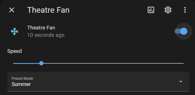
Hi folks, I have these (specifically the DCF4002WHA) working 100% as desired using Tasmota, but avoiding Tasmota autodiscovery (as the support for the MCU is poor), and also leaning heavily on raw TuyaMCU commands. This setup works in real-time and any settings applied via the remote control for the fan are reflected immediately in HomeAssistant. Fan speeds work perfectly, brightness works perfectly, and colour temps work perfectly.

The Console commands for TuyaMCU only need to enable the light and fan power. The rest is done using raw TuyaMCU commands in the MQTT config within HA.

Backlog TuyaMCU 11,1; TuyaMCU 12,9

DO NOT use the console command ā€œTuyaMCU 21,10ā€. As of Tasmota 12.4.0.5 it crashes the MCU and the entire unit will not work after a power cycle. If you ever accidentally enter this command it must be zeroed out with the console command ā€œTuyaMCU 21,0ā€ and power cycling the device.

You must also enable Option 66 via the Tasmota console and ā€œSetOption66 1ā€.
The Tasmota template is:

{"NAME":"Arlec DCF4002WHA","GPIO":[1,1,1,1,1,1,0,0,1,1,1,1,1,0],"FLAG":0,"BASE":54}

The following MQTT code works for these devices, noting you need to change your topic and device name to suit your device.

fan:
    name: "Theatre Fan"
    unique_id: "Theatre Fan"
    state_topic: "tele/tasmota_C23047/RESULT"
    state_value_template: "{{ 'ON' if '1' in value_json.TuyaReceived and value_json.TuyaReceived['1'].DpIdData == '01' else 'OFF' if '1' in value_json.TuyaReceived and value_json.TuyaReceived['1'].DpIdData == '00' }}"
    command_topic: "cmnd/tasmota_C23047/POWER1"
    payload_on: 'ON'
    payload_off: 'OFF'
    percentage_command_topic: "cmnd/tasmota_C23047/TuyaSend4"
    percentage_command_template: "{{ {1: '3,0', 2: '3,1', 3: '3,2', 4: '3,3', 5: '3,4', 6: '3,5'}[value] | default('1') }}"
    percentage_state_topic: "tele/tasmota_C23047/RESULT"
    percentage_value_template: "{{ (value_json.TuyaReceived['3'].DpIdData | int) + 1 if '3' in value_json.TuyaReceived }}"
    speed_range_min: 1
    speed_range_max: 6
    preset_modes:
      - "Summer"
      - "Winter"
    preset_mode_command_topic: "cmnd/tasmota_C23047/TuyaSend4"
    preset_mode_command_template: >
      {% if value == 'Winter' %}4,1
      {% elif value == 'Summer' %}4,0
      {% endif %}    
    preset_mode_state_topic: "tele/tasmota_C23047/RESULT"
    preset_mode_value_template: >
      {%- if '4' in value_json.TuyaReceived %}
        {%- if value_json.TuyaReceived['4'].DpIdData | int == 1 %}Winter
        {%- elif value_json.TuyaReceived['4'].DpIdData | int == 0 %}Summer
        {%- endif %}
      {%- endif %}
  light:
    name: "Theatre Light"
    unique_id: "Theatre Light"
    state_topic: "stat/tasmota_C23047/POWER2"
    command_topic: "cmnd/tasmota_C23047/POWER2"
    payload_on: 'ON'
    payload_off: 'OFF'
    brightness_command_topic: "cmnd/tasmota_C23047/TuyaSend2"
    brightness_command_template: "{{ '10,' ~ (((value | int) // 2) * 2) }}"
    brightness_state_topic: "tele/tasmota_C23047/RESULT"
    brightness_scale: 100
    brightness_value_template: "{{ (value_json.TuyaReceived['10'].DpIdData | int(base=16)) if '10' in value_json.TuyaReceived else None }}"
    color_temp_command_topic: "cmnd/tasmota_C23047/TuyaSend2"
    color_temp_command_template: "{{ '11,' ~ ((value - 154) * 100 / (370 - 154)) | round }}"
    color_temp_state_topic: "tele/tasmota_C23047/RESULT"
    color_temp_value_template: "{{ (154 + (value_json.TuyaReceived['11'].DpIdData | int(base=16)) * (370 - 154) / 100) | round if '11' in value_json.TuyaReceived else None }}"
    min_mireds: 154
    max_mireds: 370

A summary of the code is that it uses raw TuyaSend commands to make changes, and reviews the Tasmota MQTT Tele commands which - via the use of Option 66 for TuyaMCU - includes the raw status of all the dpIds and parses those for the value it is looking for.
image

I’ve just done my second DCF4002WHA using the code I posted above and confirmed it works on this second device. For this unit, I used a TYWE2S based on the ESP8285 and the only difference was that I did not need to wire up the EN pin as I believe the TYWE2S board has this hardwired to VCC.

Replying to a question from @Kaldek here for everyone’s benefit:

Hi mate, I just completed getting these ceiling fans working perfectly via Tasmota but didn’t notice your post until I was done. I didn’t do any work on the TX pin for managing the 5v from the MCU and mine seems to be stable. I’m using the Tuya TYWE3S module.

Thoughts on why this might be the case? I did solder my module onto the pins on the existing daughterboard, as I assumed the capacitors were put there for power filtering.

IIRC, I was originally testing with an ESP-01 module without any protection. It started to misbehave after a while. I identified the 5V IO, blamed the instability on this and added the series diode. No issues since.

The TYWE3S datasheet specifically says V_IH=VCC which is nominal 3.3V max 3.6V:

But then the original WR4 module has the same parameters:

Possibilities that come to mind:

  • My initial measurements were bad and there’s no 5V IO. Diode resolving instability was a coincidence.
  • Arlec didn’t read the WR4 datasheet, are driving its GPIO beyond spec and getting away with it. WR4/RTL8710BN more tolerant than ESP8266.

I recently cooked a Lolin ESP32-S2 Mini by trying to control a roller door with open drain output from the ESP. I can’t recall if the roller door was pulling that input up to 5V or 12V, but now I’m extra paranoid about exposing my ESPs to >3.6V under any circumstances.

It may now be possible to flash the LibreTiny port of ESPHome directly onto the original WR4 module which uses a RTL8710BN.

https://docs.libretiny.eu/docs/projects/esphome/

How easy is it to remove the control module from these fans if they’re already up on the ceiling?

i migth have to pull my deck fan down tomorrow in the daylight, and see whats under the hood, and potentially see if i can flash it as per your comment above.

So just confirming if I just want to use HA for the ceiling fan speeds and making some timers etc, i wont need to do any flashes? It will just connect to HA? Im still a noob to all this

I’ve had success flashing ESPHome to the WR4 inside an arlec ā€œSmart Madridā€ DCF4002WHA ceiling fan. I’ve written up some rough notes and screenshots here: projects:arlec_smart_fans:overview [Travis' Wiki]

That worked really well thanks Travis. You got RX and TX the wrong way round
on your USB-TTL serial adaptor wiring diagram, but I will let you off. Great work on your write up/documentation on this and the rest of your projects - much appreciated.

Hi team, sorry to hijack your thread, I have a similar control board without wifi and would like to add a manual rotary switch to control it. Is this possible?

Hi,

Just wondering if you need a second power supply for the WR4 module or does it get power from the TTL module USB input?

Yes, separate power supply. The 3.3v line drew more power than my usb-ttl adaptor could provide.

thanks for your help

Thanks to Travis’s information I got the WR4 chip reprogrammed to ESP home on this fan model. I think it was the Boston from Bunnings (DCF5240HA/DCF5242HA)

These are some notes that I took to help me do it.

• Use 6pin FT232RL TTL UART Board, not the 5 pin CP102 Board
• When removing the WR4 Board from the Fan controller Board, check which socket holes you remove the WR4 chip from on the fan controller board as they can go in two positions.
• Use an alternate 3.3V power supply for the powering of the WR4 chip not the UART board
• Use fine solid core cables for soldering to the WR4 board. I used some Cat6A strands
• I didn’t solder the GND, 3.3V or RST pins to the WR4 board. I Just use some jumper cables and crush slightly with a pair of pliers to fit
• To obtain the uf2 file from ESP home, create a config in ESPhome and then from ESPhome install the config, then select download. Mine failed and threw up errors. After some researching the file was too large. Delete any unnecessary comments or configuration in the YAML file and try again
• When Flashing the chip with the ESPHome uf2 file select the Realtek AmebaZ chipset.
• If testing the WR4 chip in home assistant without being connected back to the fan controller board the fan switch does not work. Once connected it will work
• When putting the WR4 Chip back in the fan controller board, make sure to reclip the aerial back on.

Also an updated drawing

This was my ESPhome YAML file

esphome:
  name: arlec-fan-light-3
  friendly_name: Arlec Fan Light 3

rtl87xx:
  board: generic-rtl8710bn-2mb-788k

api:
  encryption:
    key: "xxxxxxxxxxxxxxxxxxxxxxxxxxxxxxxxxx"

logger:
  
ota:
  - platform: esphome
    password: "xxxxxxxxxxxxxxxxxxxxxxx"

wifi:
  networks:
    - ssid: xxxx
      password: xxxxxxxx
      priority: 1

uart:
  rx_pin: GPIO18
  tx_pin: GPIO23
  baud_rate: 9600  
  
tuya:

fan:
  - platform: "tuya"
    name: "Bed 2 Fan"
    switch_datapoint: 1
    speed_datapoint: 3
    direction_datapoint: 4
    speed_count: 6

light:
  - platform: "tuya"
    name: "Bed 2 Light"
    switch_datapoint: 9
    dimmer_datapoint: 10
    min_value: 2
    max_value: 100
    color_temperature_datapoint: 11
    color_temperature_max_value: 100
    color_temperature_invert: false
    cold_white_color_temperature: 6500 K
    warm_white_color_temperature: 2700 K

Thanks again Travis, I could not have even got this far without the great work you have done

I’m having a very weird one with my grid connect fans. I have two units which are the same model, and have the same configuration in LocalTuya, but are not functioning identically…

Both report the same firmware (Main module V1.0.5 and MCU module V1.0.1)
Both show the same model when I query device details via the Tuya API (ā€œproduct_idā€: ā€œ4car5fldnnmdx17yā€, ā€œproduct_nameā€: ā€œCeiling Fan DCF5240HA/DCF5242HAā€)
Both have the exact same config for the fan entity
Both have the exact same config for their light entity(Brightness 10, Color Temp 11, Brightness values 5-100, color temps 2700-6500

The difference? The bedroom light doesn’t turn off/on when I press the power button in the entity view. I have managed to bodge a workaround by adding a third entity, type Switch, with no details other than a friendly name. That has let me turn the light off and on, but I am absolutely perplexed as to why this is the case (and it’s annoying to have to adjust brightness/colour temp in one entity and power in the other)

Can I just force HA to merge these two entities somehow?

Update - I evidently just needed to spend another night bashing my head off the desk before I realised the problem. Despite showing as identical units in software, the two devices had different product codes on the physical label. One was a DCF5240HA, one a DCF5242HA

LocalTuya was assigning an incorrect DP/ID to the light entity on the problem unit (the DCF5242HA), setting it to 3 rather than 9. Because I was reviewing the config of both after they had been added, I didn’t pick up on it. Changing that has now gotten things working as intended.

Hello,

First of all, many thanks to everyone who opened the topic and wrote a comment because it is a topic I have been looking for a long time.

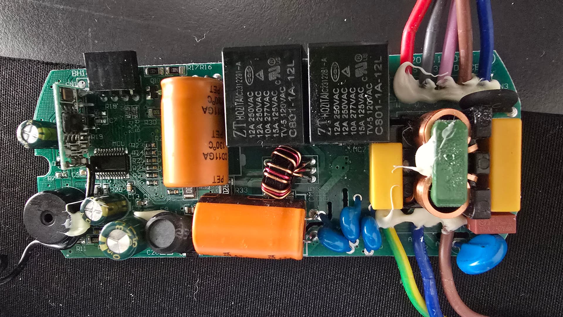
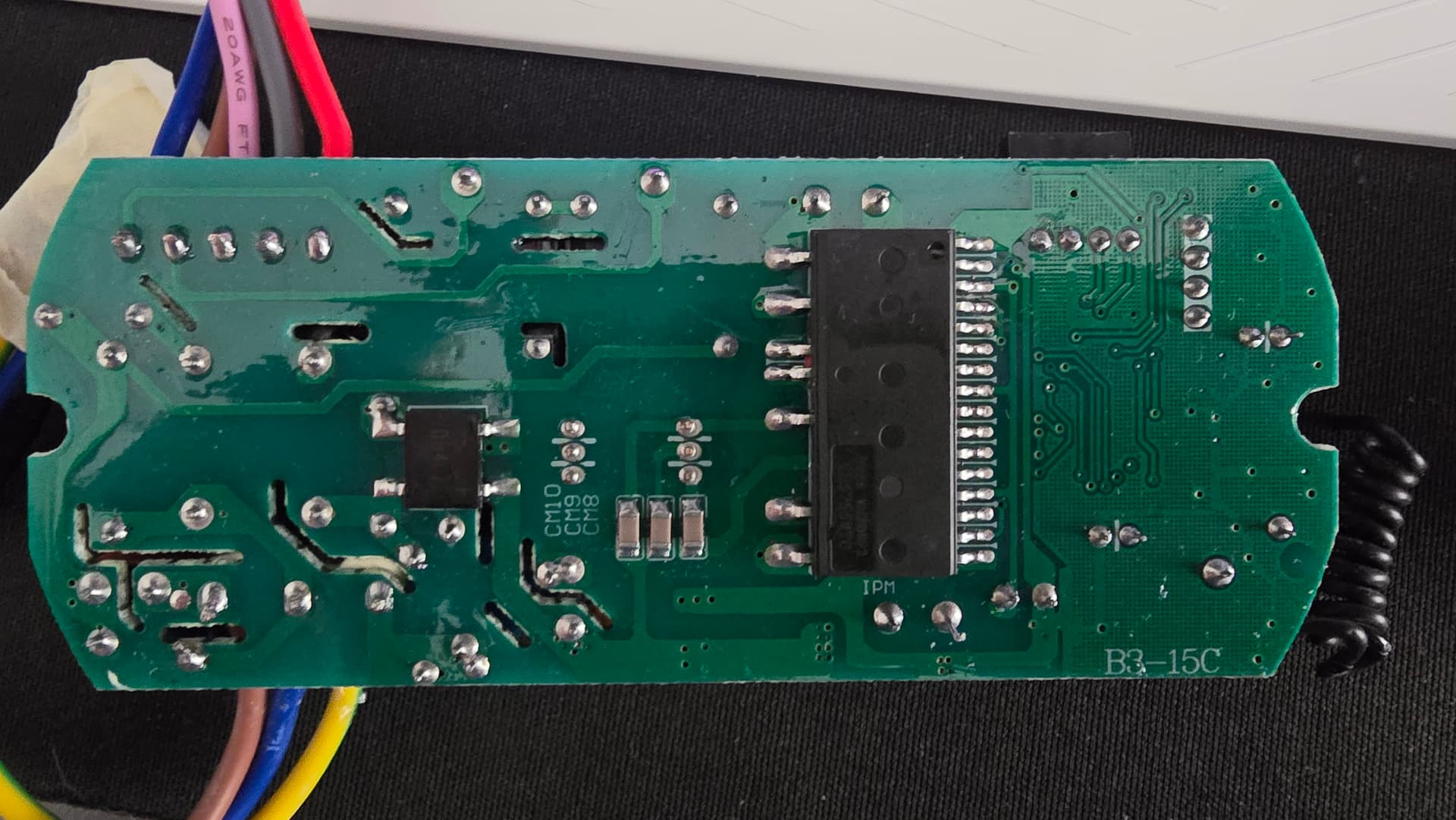
I have been researching for a long time to integrate it into my Home Assistant with ephome for the B3-15C RF controller with 6 fan speed options and light control, which I have attached the pictures below.

I don’t think I can find a one-to-one source with the controller, but I don’t think I can come close. Because I couldn’t find a data sheet for the controller and this title gave me a lot of hope.

Especially with the 4 pins next to the controller, I think I will receive and transmit data with RX, TX, but I still need serious help from you masters for the result. Can I integrate this card directly to my Home Assistant via esp32/esp8266/esp mini or esphome with a different card?

Thanks in advance for your help and comments.
Regards.


It would be a lot more helpful if you provided details for the ā€œsmart ceiling light/fanā€ kit, rather than some markings on the pcb board.

Not to be rude but, if you want help with a product/device then at least provide product link to where you bought it or anywhere online so we can see what you’ve got. Myself and others are happy to try and help you but, its just kind of irritating when i myself or others have to go do some Google searching to try figuring out what this mystery device brand/model number etc is and i just wasted 5min searching for ā€œB3-15C RF Controllerā€ and couldn’t figure out which one matches yours because vendors dont typically list items using codes printed on the pcb’s and instead use the information printed on the box or the device itself.

Post more specific details and help us be able to help you better!

It would also be helpful to know upfront if you know which frequency it uses, whether its 433mhz, 315mhz, etc.
Also, can you elaborate on what exactly your goal is here? I assume you already have the original controller that came with the module and now your wanting to integrate it into HA but, you also mention looking for a ā€œone to oneā€ source for it which i can only assume is a second controller?

I assume what you want to do is use the original remote and have HA see/detect when someone uses it to change fan speeds/light etc and display the current light and fan state in HA as well as sending new fan/light states from HA itself, right?

Have you already tried anything like an RF bridge/hub like the Broadlink Integration for HAor Sonoff RF Bridge? What about capturing the codes with an esp board and an RF receiver? Once you capture the remote control RF codes then you can retransmit them from another RF transmitter or potentially using a generic RF remote that you can program yourself, similar to how a universal remote works for a tv.

433mhz 4-channel transmitter and receiver that can be programmed to transmit any RF codes you want so that each Input like if you wanted 4 buttons then each button press would cause the receiver to transmit an RF code for example 4 buttons could be Speed+, Speed-, Light Dim+, Light Dim- if that makes sense.

4-channel transmit and receiver

Here is a plain old transmit and receiver that could listen for your remote control then send updates to HA using the receiver and with the transmit you would that to send RF codes from HA using Esphome.

RF Transmitter/Receiver

Have you tried anything at all so far?

Its pretty simple to just pick up a pair of transmitter and receiver, capture the buttons codes then set them up in Esphome/HA. I have like 4 of those conversion kits that are all different brands like this is one of them for example. Thats the exact method i used to integrate them all into HA.

Thanks.

Fan/light RF smart kit

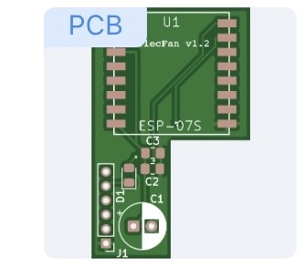
I’ve got 30 spare boards if anyone interested.
They are similar to OPs ones, but with 6 pin headers, a few mm shorter and surface mount diode.

I haven’t been confident to try and put one together as I’m not great with a soldering iron. Would you sell these fully build with esphome loaded and ready for adoption and customisation?

I’m happy to give these boards away, offer advice or help out locals with soldering they may not be confident with, but not really looking for additional liability that would go with a fully assembled board.