Arlec Grid Connect Ceiling Fans

May 2023 update

I’m all out of boards. For new Arlec fan owners, I’d recommend checking out:

  • LocalTuya, local control of the fans without any hardware/firmware modification.
  • Flashing LibreTiny ESPHome firmware onto the WR4 module (RTL8710BN based).
    • Hopefully also compatible with my patch to correct the colour temp / brightness curve
  • Others in this thread who have made their own boards

Original post

Hey all,

I’ve recently spent some time trying to integrate my Arlec ceiling fan with Home Assistant. The original Tuya WiFi module isn’t ESP based, so Home Assistant integration via ESPHome was achieved by designing a simple replacement WiFi module. I introduced this project with some more background over in the Australian electrically certified thread: Australia - Electrically Certified Hardware - #2707 by rymo Others have expressed interest, so I think it’s time to start a dedicated thread to keep track of things.

Compatible fans

All of this was tested with the DCF5242HA “Smart Boston” - which includes a dimmable CCT light. The cheaper fan-only models reportedly have the same WiFi module, so I hope that this procedure also applies to those.

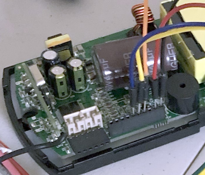
Disassembly and reverse engineering

The controller is easy to open after disconnecting external cables - 2 screws on the bottom and 2 plastic clips on the sides. The original WiFi module pops right out. Note that the mainboard has a 10 pin header while the WiFi module only has 9 pins - the module should be installed closer to the buzzer.

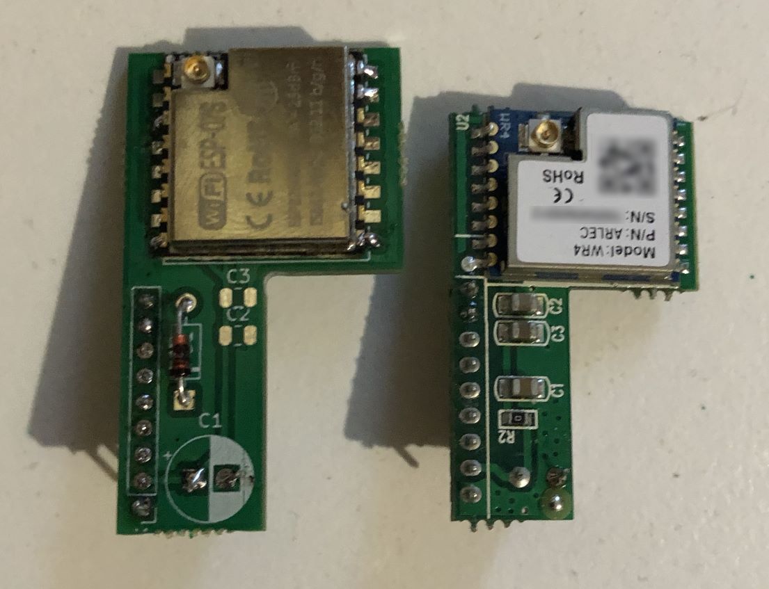
The pinout of the original WiFi module is helpfully marked on the reverse side - unfortunately I only discovered this after tediously buzzing out each pin and cross-referencing with the Tuya WR4 datasheet. I’m unsure when RST is brought low by the MCU, so I’ve just ignored it. UART TX from the MCU is surprisingly 5V, which is an issue as the ESP8266 is not 5V tolerant. This caused stability issues in my original testing until I narrowed it down with the oscilloscope. The ESP8266 UART RX pin has an always-on 3.3V pull-up, so the simple solution here is to use a diode. When fan TX is low, the diode is forward biased and ESP RX is pulled down to ~0.7V through the diode - low enough to be considered logic low by the ESP. When fan TX is high, the diode is reverse biased so no current flows and the ESP’s internal resistor pulls up to a safe 3.3V.

Now’s probably a good time to mention an IMPORTANT SAFETY NOTE, which is that the fan controller electronics are not electrically isolated and thus always referenced to MAINS VOLTAGE. You should NEVER TOUCH OR INTERFACE WITH THE FAN CONTROLER WHILE CONNECTED TO MAINS POWER, and you should also SAFELY DISCHARGE CAPACITORS before touching anything on the control board. Oh, and test your RCDs - they could save your life.

In order to probe the board with an oscilloscope to figure out the stability issues I had to use a dodgy un-earthed travel adaptor to isolate the scope. Never do this without knowing exactly what you’re doing, as this meant that the exposed metal parts of the scope were at mains voltage while I was working!

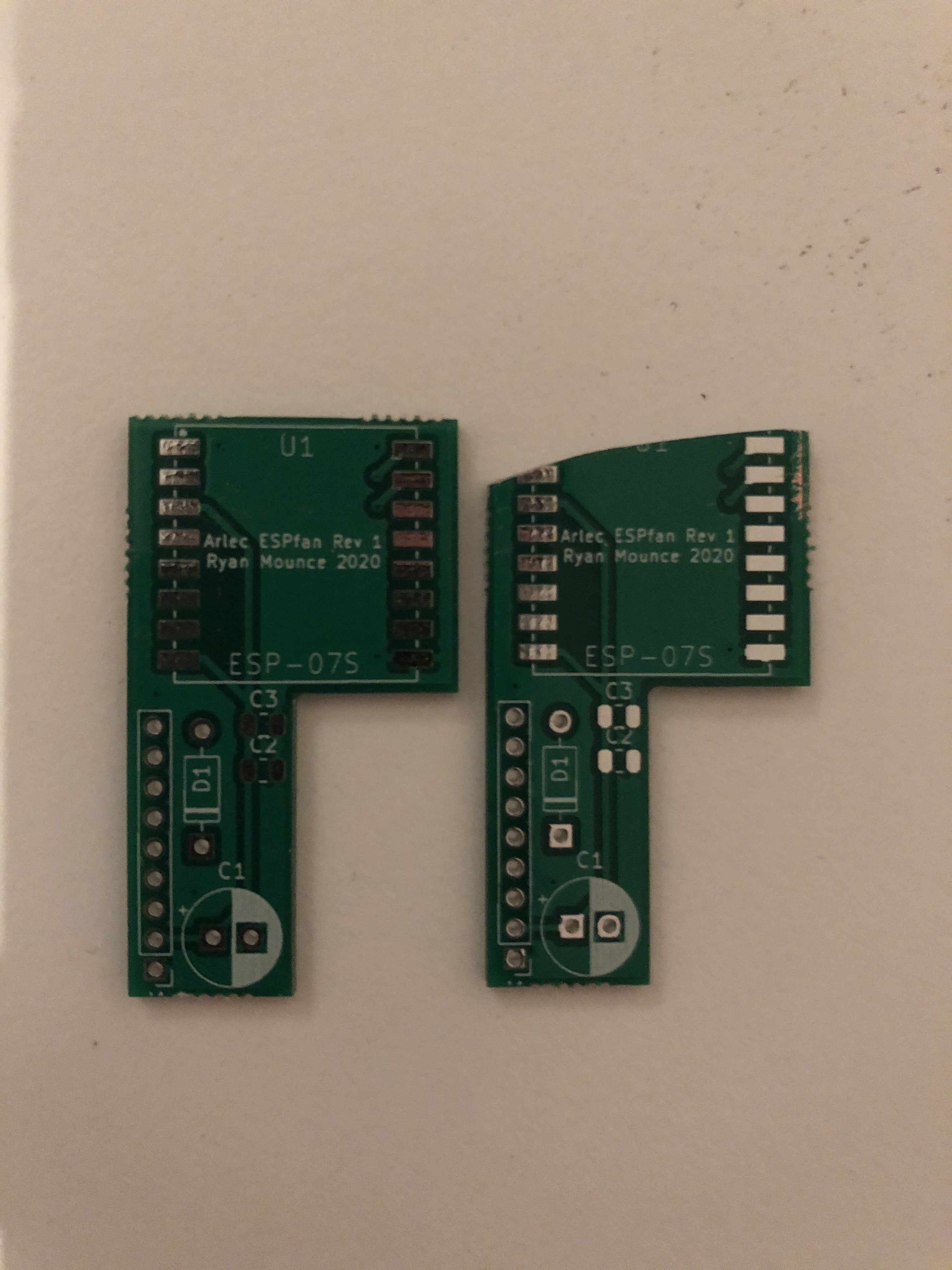
Replacement board design

In the end, I came up with the following dead simple schematic for the replacement board, based on my prototype consisting of an ESP-01 and a breadboard. I don’t know how many decoupling capacitors are really needed - I’ve modelled this aspect on the original module. In practice I’ve left the ceramic caps unpopulated because I’m bad at manipulating tiny surface mount parts and it seems to work anyway :slight_smile:

Mechanically, the board mimics the original - using an ESP-07S module in place of the Tuya WR4. Everything was designed in KiCad, which was a straightforward and pleasant experience as someone who hasn’t designed a board since using Altium at uni years ago. Project files here: GitHub - rmounce/ArlecFanESP-PCB

I got the boards fabricated by PCBWay based on a couple of recommendations from professional EEs. The total cost for 5 panels of 10 boards each was 49 USD, most of which went towards shipping and paying them to panelise the boards. To my untrained eye I think they did a nice job, and even threw in a cute little xmas tree board with colour changing LEDs.

Unfortunately, I underestimated the extra length of the ESP-07S module and included an unnecessary margin between the pin header and the module - meaning the board only fits into the enclosure if it is on a slight angle resting on the 433MHz module. For the next next batch of boards I would swap to an 8 pin header and shorten the board by 3mm for the ESP-07S to fit snugly between the big cap and the 433MHz module. To get the current boards to fit more comfortably I’ve only soldered on the first 6 pins that are actually used, this way the overall connection is looser and easier to angle as necessary.

The above picture is after wedging everything into the enclosure, note how the WiFi module is pressing against the cap on the 433MHz board. I’m not keen on this… but it hasn’t caused any issues so far.

Assembling and flashing

The bill of materials for each board I assembled is nice and short

After assembly, I flashed the board by tacking fine wires onto the pads. I used esptool.py to flash my pre-baked ESPHome image - however you may find it more convenient to use e.g. Tasmotizer to flash a generic Tasmota image and then flash ESPHome over the air.

GND - GND
VCC - 3.3V
IO0 - GND (for flashing)
ESP TXD0 - USB UART RX
ESP RXD0 - USB UART TX

image

Once flashed I just inserted the new module - connected the antenna and carefully snapped the plastic enclosure back together. Don’t use too much force or you could damage the 433MHz module.
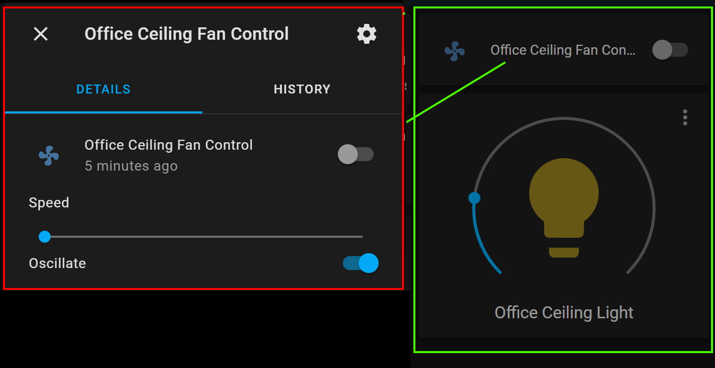
ESPHome config

In conjunction with a couple of ESPHome patches to unlock the full functionality of these fans, the below config “just works” in conjunction with Home Assistant.

Updated May 2023

substitutions:
  device_name: "arlecfan1"
  friendly_name: "Arlec Fan 1"

esphome:
  name: "${device_name}"

esp8266:
  board: esp01_1m

wifi:
  ssid: !secret wifi_ssid
  password: !secret wifi_password
  ap:
    ssid: '${device_name}'
    password: !secret fallback_password

captive_portal:

# Enable Home Assistant API
api:

ota:

logger:
  # Disable UART logging as these pins are used for Tuya MCU comms
  baud_rate: 0

uart:
  rx_pin: GPIO03
  tx_pin: GPIO01
  baud_rate: 9600

tuya:
# DP1   Fan On/Off
# DP3   Fan speed 0=lowest, 5=highest
# DP4   Fan direction 0=summer, 1=winter
# DP9   Light On/Off
# DP10  Light brightness 0=min, 100=max
# DP11  Light temperature 0=cool, 100=warm
# DP102 ?
# DP103 ? Timer value, 0=off, 1=1h, (2=2h?), 3=4h, 4=8h
fan:
  - platform: "tuya"
    name: "${friendly_name}"
    switch_datapoint: 1
    speed_datapoint: 3
    speed_count: 6
    direction_datapoint: 4

# Optional patch to correct colour temperature / brightness curve
external_components:
  - source: github://rmounce/esphome@tuya-temp-correct
    components: [ tuya ]

light:
  - platform: "tuya"
    name: "${friendly_name}"
    switch_datapoint: 9
    dimmer_datapoint: 10
    min_value: 2
    max_value: 100
    color_temperature_datapoint: 11
    color_temperature_max_value: 100
    # 1000000 / 5700 K = 175.43
    cold_white_color_temperature: 175 mireds
    # 1000000 / 3000 K = 333.33
    warm_white_color_temperature: 333 mireds

Getting a board

I’m not fully across this whole eCommerce thing, nor business for that matter! If this becomes popular I’ll try listing on Tindie? In the meantime in exchange for each $10 AUD donated (plus $10 for postage) I’ll happily post you a board within Australia, and even throw in a cap (of the electrolytic variety), a length of pin header, and a diode! Strictly BYOESP. Send me a DM to arrange.

-Ryan

11 Likes

just what i am looking for :slight_smile:

@oziee had the idea of filing down the board to improve the fit, which I’ve since attempted. There’s still a bit of contact between the WiFi and 433MHz daughterboards, but there’s noticeably less pressure between each board. I’ve also added some kapton tape to avoid any shorts from the filed down board, as the glimmer of the ground plane is visible on the edge. And also on the top where the solder mask is wearing off… I think that’s down to how I held the board with my bare hand while filing it.

I’ve replied to everyone who’s interested in boards, and will send out the first batch this week.

-Ryan

We must have purchased these fans about the same time. I was shattered when i opened it and saw the tuya chip and at the time there was nothing in any community about integrating / converting these at the time. I looked. Only various posts of people having bought devices that use to contain esp modules and now they contain tuya ones and they’re incompatible etc, and oh yeah, tasmota posts about not supporting realtec chipsets (understandably).

Anyway, tonight I came across digiblur’s YouTube about a very similar problem in a seperate controller. In following links from that page, notably Wydra’s post about a TreatLife conversion he did. From there it was only a few searches later looking for compatible ESP pin outs to the tuya WR4 module that I finally ended up here… and glad I did too! Like I say, we must have been probing the boards about the same time.

Unfortunately I was working on completing a garage conversion, kids and a business to manage over Xmas and so I put it all back together with the idea, “I’ll get to it one day”… coming across digiblur’s video a couple of hours ago, I decided it was time to revisit!

Something I wanted to ask you thought, at the time I was probing the board I wasn’t in a position to run a powered test, but concluded the wifi mini board in this fan was merely a means of wifi communication to the mainboard underneath. Given the RF daughterboard and the wifi daughterboard both couple to a mainboard containing an ARM Cortex M0 running at 48MHz (I believe its this one), I considered the “smarts” of the fan were all controlled there and the tuya wifi would only be sending serial commands to it. For a moment I thought that maybe the wifi connection (SSID, password and comms) were actually controlled by the ARM and the tuya chip was simply used as a bridge! Because of that, I considered I might reverse engineer the RF comms instead and I was going to inject fan control there because I had no idea where I was going to start with the ARM processor!

I plan to put Tasmota on mine, purely because that’s how I have everything integrated already, and I’ve never looked at ESPHome, although since you’ve done that work I feel I should at least investigate it.

This was a long way to get to one of my main points:

  1. what did you determine to be the connection/communication method between the wifi and the main ARMprocessor underneath? What commands are you sending to it? Is it some sort of serial data “set fan 0-6, set light colour/brightness”?
  2. One of my main questions, are we able to poll the fan/light for it’s current value? Does the main unit report back current values and changes that have been made by the RF control?
  3. What are the ESPHome “Patched” you talk about? You mention them but don’t elaborate at all. I think this may be what I was eluding to above with the smarts being controlled by the underlying ARM processor
  4. Last point is just that AMAZING work, very impressed! AWSOME! Do you still have some boards? I’ll reach out via DM to discuss this more

Very happy to have stumbled across this tonight… err this morning (it’s now 5am and I should have been in bed hours ago)

Cheers!

Hi Dave,

I didn’t even get as far as you in identifying the MCU used on the fan’s mainboard. I just figured out the pinout by probing the WiFi daugtherboard & cross-referencing the Tuya WR4 datasheet, and hoped that the comms between the two was based on the “Tuya MCU” protocol over UART that has already been reverse engineered and implemented in ESPHome by others: https://esphome.io/components/tuya.html

Without any explicit configuration this component in ESPHome enumerates & dumps values of all “datapoints” exposed by the MCU. So I just played with the RF controller & observed the dumped values to identify the purpose of most of the datapoints. When configured with fan & light components in ESPHome the state in Home Assistant is instantly updated when the fan speed / brightness is changed from the RF controller. The state change messages from the MCU are part of the Tuya UART protocol & implemented by ESPHome - so long as everything “just works” I’m happy to remain ignorant of the low level protocol details so I honestly don’t know if these are polled for changes in a tight loop by the WiFi module or if the MCU sends unsolicited updates.

The “patched” ESPHome is https://github.com/rmounce/esphome/commits/mine
I’ve just added support to control the colour temperature of the light on these Arlec fans, and incorporated someone else’s change to allow remapping of low/med/high fan speeds to arbitrary values rather than being limited to a max fan speed of 3. I’ve submitted a pull request for the former which I hope will be incorporated into ESPHome proper & also provided some feedback to the author of the fan speed remapping change - so I hope that I can stop maintaining my slightly customised ESPHome soon.

Somone else has DM’d me requesting assistance getting my tweaked ESPHome build up and running so I may attempt to write that up soon.

Will reply to you privately to see that you get your hands on some boards.

-Ryan

The work you have done here is awesome Ryan. I just had two of these fans installed today and I have a friend who has several. We both run Hubitat and don’t currently have Home Assistant but due to your work on this we are both going to setup Home Assistant for this integration. I’ve just joined this community having found your post. I’m not sure how to DM you atm but I would like to contact you about getting several boards.

Thanks for you great work.
Scott

I think I’ve replied to all DMs re: getting boards. I’ve cleaned out my local Jaycar of the caps & diodes, so I’m running a bit low on supporting components and just ordered a larger batch.

I was hoping that my PRs would be reviewed & merged a bit sooner so that I could point people to use the upstream stable version of ESPHome - but in the meantime here’s my terse attempt at documenting the command line setup process to build an ESPHome image from my tweaked branch.

Tested on Ubuntu 20.04. Similar procedure on macOS/Homebrew. WSL is now a decent option for Windows people. Users of non-Debian-based distros are surely used to translating instructions from apt by now :stuck_out_tongue:

sudo apt update
sudo apt install git python3-pip nano
git clone https://github.com/rmounce/esphome.git
cd esphome
script/setup

from this point things are pretty much the same as Getting Started with the ESPHome Command Line — ESPHome just ensuring that we’re in the directory with esphome cloned and running python3 esphome as esphome isn’t in our $PATH.

mkdir config
nano config/arlecfan1.yaml

paste in the config from my first post in this thread, updating names and wifi details as required
connect your board to USB serial & power, pull GPIO0 down to GND

python3 esphome config/arlecfan1.yaml run

Or in my case i actually ran

python3 esphome config/arlecfan1.yaml run

… then copied config/arlecfan1/.pioenvs/arlecfan1/firmware.bin to my workbench laptop & flashed with esptool.py since i’m familiar with that process. This file should also be flashable via the Tasmota webUI to convert to ESPHome.

all done now… i used Tasmota not ESPHome… all working great now :slight_smile:

1 Like

Firstly a big thank you to rymo for all his work on this.

I manage to get it all working and I’m fairly useless and new to home assistant and esp8866.

Two problems were as follows.

  1. Flashing the esp07s. I couldn’t get the chip to flash. I have previously had little problems flashing with other smart devices, however I was using the fdti usb to serial power the chip. That output was 5v and the boards I was flashing already managed the 3.3v to the chip. In this case I needed to give 3.3v directly to the chip. I used a raspberry pi to provide the 3.3v. However I could seem to flash the chip unless I tied the ftdi ground to the chip ground… not sure if that was a coincidence or not. Maybe I was doing something else the first few tries.

  2. I used esphome via a hass.io install. I couldn’t get the custom patched firmware working. And couldn’t even install using the instructios as hass.io is so locked down. Thankfully the suggestion to use WSL and Ubuntu to generate the firmware worked out well.

At this stage I have control via home assistant.

It would be nice to get all 5 speeds selectable and rename the oscillation to winter/summer. But I’ll tinker around next week to see if i can. 8 just brute force stuff so it might never work.

Anyway. Thanks to rymo again, and hope any of my failures can get you past if you are stuck.

1 Like

Hi All,

Can someone please help me.

This week I’ve successfully used Tasmotizer to flash the module with a generic Tasmota image.

I’m upto the point of building the firmware with WSL2.

Do I need to populate these in the ESPHome config:

#Enable Home Assistant API
api:
ota:

My understanding is that once I create the firmware file and can update it OTA via the Tasmota web gui. Is this correct?

One last thing before I create the firmware, is there any updates to the “ESPHome config” I should make?

Thanks

Hi Scott

I think api and ota are required, even if they are blank. These are the passwords you then type in to initially connect or run ota updates. I have a password set on mine, I just use my wifi password. I have them all in a secrets.yaml.

I didn’t need the light section in mine…as my fan doesn’t have a light. Don’t know any other updates to the config. I haven’t had a chance to play and see if I can improve the config to get more precise control of the fan. I know they have gone across to percentage based speeds on home assistant and will be depreciating fan speeds eventually. This is good I think as it will make it easier to get all of the speeds… maybe I’ll get around to playing with it one day when life doesn’t get in the way. I’m slowly learning.

And yes, upload the ESP firmware via tasmota, I did have some issues uploading initially I think but that was more a networking issue, the mDNS didn’t work, I ended up hardcoding the IP first, then changing to the mDNS.

substitutions:
  device_name: f_bed1
  friendly_name: "Bed 1 Ceiling Fan"

#################################

esphome:
  platform: ESP8266
  board: esp01_1m
  name: ${device_name}
  esp8266_restore_from_flash: true

wifi:
  ssid: !secret wifi_ssid_iot_study
  password: !secret wifi_password
  fast_connect : true

  ap:
    ssid: ${device_name}
    password: !secret ap_password

captive_portal:

api:
  password: !secret api_password

ota:
  password: !secret ota_password

logger:
  # Disable UART logging as these pins are used for Tuya MCU comms
  baud_rate: 0

uart:
  rx_pin: GPIO03
  tx_pin: GPIO01
  baud_rate: 9600

tuya:
# DP1   Fan On/Off
# DP3   Fan speed 0=lowest, 5=highest
# DP4   Fan direction 0=summer, 1=winter
# DP9   Light On/Off
# DP10  Light brightness 0=min, 100=max
# DP11  Light temperature 0=cool, 100=warm
# DP102 ?
# DP103 ? Timer value, 0=off, 1=1h, (2=2h?), 3=4h, 4=8h
fan:
  - platform: "tuya"
    name: ${friendly_name}
    switch_datapoint: 1
    speed_datapoint: 3
    # This works, but isn't plumbed all the way through to Home Assistant frontend
    # Requires https://github.com/esphome/esphome/pull/1409
    # direction_datapoint: 4
    # Instead, oscillating = winter mode
    oscillation_datapoint: 4
    # Requires https://github.com/esphome/esphome/pull/1391
    # further enhanced by https://github.com/rmounce/esphome/tree/tuya-fan-speed-tweaked
    speed_value_low: 0
    speed_value_medium: 2
    speed_value_high: 4

Thank you very much for your quick reply Mike!!

I have done some googling after reading you post and now have a better understanding around the use of api: & ota:.

I hope to get this up and running over the weekend :slight_smile:

Hi All, I’m brand new too HA so there’s been lots to learn. I discovered today that it’s possible to integrate the fan/light with local tuya without replacing the wifi module and have successfully set this up. Can someone please tell me what the advantages are of the ESPHome integration by replacing the wifi module vs the Local Tuya integration?

As a user of both localtuya (for my Arlec grid fan) and esphome I think the advantage of esphome is better integration and far more customization. Although for a lot of prebuilt tuya devices I have found that I just end up replicating the function of the original device in esphome and putting the smarts in HA.

I think the main reason for not using localtuya at the moment is the maturity of the project. But this is a chicken or egg scenario as the project needs more users and contributors to become better.
The local keys are a bit tricky to get but this is no more skill required than flashing esphome.
Another consideration is that you are relying on tuya to keep the localapi open/unchanged. With the recent tplink api issues this is never a given. You can mitigate this by blocking them from the cloud though once you have them integrated.

The reasons I am giving localtuya a shot is that if /when I sell the house I want to be able to just reset the devices and leave them for the next owner. With tuya I can do this.
As this project/thread is a controller replacement you can always go back to tuya if you want. This is not an possible and/or easy process if you reflash an onboard controller.

I have posted on the au hardware thread with some more detail. Link
I do plan on writing up a more detailed post and contributing my finding/changes to the localtuya project.

1 Like

Thank you Tim for such a detailed reply, I found it very helpful. I think I’m going to see if the Local Tuya integration meets my requirements.
When I get more time I’ll continue with replacing the wifi module so I can see first hand the differences. I’ve already built the new wifi module, just need to flash it with the ESP firmware I built today.

@rymo I’m not sure how to DM you on these forums, so this will have to do.

I have three of the 433MHz arlec ceiling fans and I’d like to integrate them to HASS without having to go via the terrible 433MHz interface. Do you have any more of those boards left? The board in the non-gridconnect version has the same footprint as the ones in your photos, though without the 0.1" SIP socket populated.

Cheers,
tjhowse.

@rymo

I’ve received the boards, soldered them up and flashed them with esphome. Thanks! They were super easy to integrate into hass too. So far so good.

I could power the boards up on the bench, and they’d connect to hass, however they wouldn’t power up when inserted into the fan controller. I suspect the older pre-tuya arlec fan controller boards I have don’t have the components populated to route from the J2 header over to the smarts:

The 6x1 SIL header you see on the board was crudely unsoldered from the J3 header visible in the bottom left, then straightened and soldered back on at J2. I read ground on J2 pin 1 (rightmost in this picture), but as far as I can tell it’s not getting 3.3V on VCC, based on there being no continuity between J2 pin 2 and the VCC pin on the 433MHz radio on the left of the board.

There’s a bunch of suspiciously empty pads just up from J2. I suspect on the non-gridconnect versions of this control board J2 is not usable in this way.

Do you happen to have any photos of your fan board disassembled, showing the PCB underneath the wifi daughterboard?

Cheers,
tjhowse.

@tjhowse these are the only pictures I have on hand. My fans are still in box (waiting for house build) so if I get a chance I’ll try and get a better shot.

Looks like you have a different MCU as well as some unpopulated components, though the presence of the J2 header suggests that it may still be Tuya compatible?

Nice project Rymo, Love the circuit board replacement idea.

I ended up going down another path, which tinlis1 mentioned. And I did get two Arlec Grid Ceiling Fans setup with Localtuya in Home Assistant (No cloud apart from the initial setup)

Basic Steps:
Install HACS on HA, Setup LocalTuya
Pair the Ceiling Fans (and all other grid devices while you are at it) with the “Smart Life” app on your Mobile
Setup an Rooted Android emulator and sign in with that Smart Life account. (Youtube guides)
Dig out the XML file from the app and locate your device keys
Setup the ceiling fan in HA, Select LocalTuya intergration, Pick the device from the dropdown and enter the key. Match the attributes as per screenshot, Setup two devices, one Fan the other Light.

Finished Result in HA

Attribute info - Credit @tinglis1
DPS [1] VALUE [True] → fan on,off > True, False
DPS [3] VALUE [6] → fan speed > 1-6
DPS [4] VALUE [forward] → fan direction > forward, reverse
DPS [9] VALUE [True] → light on/off > True, False
DPS [10] VALUE [100] → light brightness > 0-100
DPS [11] VALUE [100] → light colour (cool-warm) > 0-100
DPS [102] VALUE [normal] → preset mode > normal, sleep, nature
DPS [103] VALUE [off] → timer > off, 1hour, 2hour, 4hour, 8hour

1 Like

There is a pull request with the local tuya integration to update to the new fan platforms and give all the fan functionality.

You can try it out by using the files from the pull request.
GitHub pull request

1 Like