My take on the whole automated roller blind if anyone is interested.
It’s direct drive so no gears to bother with, cheap and readily available parts, blinds (IKEA) from 60 to 200cm in width, both HA/ESPHome and manual controls.
all parts at:
Still working on the page so more information with clearer instructions will come in the following days.
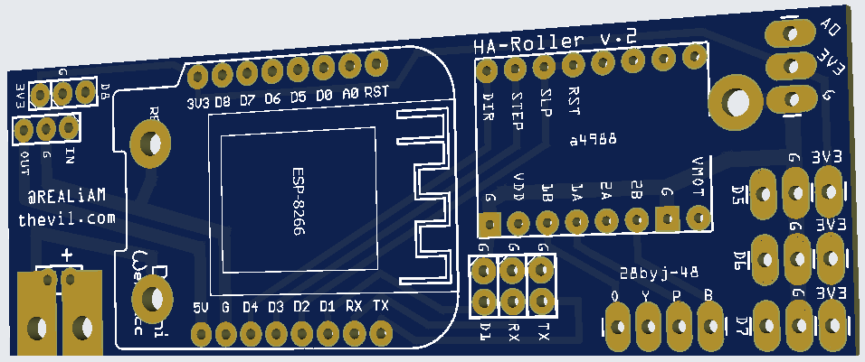
Added PCB complete with Gerber-files to my GitHub:
Code/.yaml originally expanded on the codebase from RoadkillUK.
I’ve added some features and also made both configurations into single file, with the ability to turn status reporting to HA on/off from HA itself, no need to reflash.
Anyways, it’s hosted at:
Let me know what you think and if you see any ways to improve it.
It’s been quite thoroughly tested, been running them for a couple of months myself, no issues.
Even stress tested using node-red flow with 24h continuous operation, of rolling up/down with 10 sec delay (family went crazy and had I to stop =D).i
I really like the look of this project. Good to know the Ikea blinds can still work with motors even though they don’t use the beads any more. I built some blind with jysk blinds which i don’t find a great quality. They have frayed slightly on the sides and are a little bit flimsy. How do you find the quality of the fridans blinds?
I use the 28byj-48 12v with the uln2003 drivers. I was reading on thingiverse that you use the A4988 which provides more torque. I might look at swapping these in to test.
Thanks for sharing
Actually IKEA Fridans still uses beads on a string, but they are encased in a “rod”, I’d suppose it would work by exposing them/breaking the case.
However, I wanted to use “direct drive” to not have to use ball bearings or gears (adds to size and complexity as well as looks). I find the quality of the blinds to be similair/better to the IKEA Tupplur (IKEA’s old blackout roller blind).
I haven’t tried the 28byj-48 12v only the 28byj-48 5v version (running them at ~7.5v), and the torque is more than enough for the speed I want and no heat issues.
Please report back with what speeds you achive if you try it out, would be interesting to know.
The price difference might be worth it in some circumstances.
lastly, what speeds did you get with uln2003 and the 12v? I found 5v and uln2003 frustratingly slow in order for it to be able to raise a medium to large blind.
I though the mechanism on the ikea blinds might be different and require more work to rotate. Good to know it’s straightforward.
I have a geared setup for mine as I had trouble with direct drive. The blinds were slipping and therefore getting out of sync. I wonder if the driver couldn’t deliver the required torque.
My blinds are 110cm long and take a very slow 75 seconds to open/close. The blinds range from 40-100cm in length and all take the same time. How long do yours take?
I’ve ordered the new drivers so hopefully get around to testing next week. I might test out my direct drive again with the new driver
When I used uln2003 I could only go to around 250steps/s using direct drive before ending up out of position (especially when rolling up), and they were slow, I’d imagine they go even slower with an added gear to add torque to prevent slipping.
Can’t say for other brands of blinds, but I run IKEA’s fridans 200cm in width and they open/close in -40 seconds running @ 600steps/s.
I have a 60cm one as a test-blind while developing and that could do +1000steps/s, so that was quick.
But i settled for 600steps/s so that all would move in sync and leave a bit of torque in case they drag against anything in the window (flowers/lamps/curtains).
I would recommend direct drive if you got access to a 3d printer, there are only two things that you HAVE to print: the holder for the motor and the insert for the roller.
The assembly pretty much makes it look factory-made, the motor is secured by the holder that comes with the blind, this is if you buy the Fridans blind from IKEA of course.
I’m adding a “cover” to my thingiverse page to give and even cleaner look.
uln2003 runs the stepper in unipolar mode and a4988 runs it in bipolar, so the red wire from 28byj-48 is never used, this in turn gives greater torque=speed.
I got my new drivers and tested out on one blind. I was able to direct drive at 600 steps which I couldn’t do previously. I was able to run at about 450-500 steps on a direct drive with the ULN2003. The blind open/close time was cut in half. I wasn’t able to increase the steps on a geared setup with the A4988
I’m going to test on one of my bigger blinds once I tidy up my wiring
Are you still running the 12v version? How much voltage do you currently supply?
I would have guessed you could have gone faster since I get the same speed with a 5v stepper at 7.6v.
@realiam Love what you’ve done here, I’ve had the Fyrtur Ikea blinds but the Zigbee hasn’t been reliable / I have some windows larger than their max size so this looks ideal.
I haven’t used the A4988 driver before, did you find one with a socket like all the ULN2003 ones or did you solder the stepper motor directly to it?
I don’t fully understand what the ikea fixa is used for, did you manage to get a pcb layout / wiring diagram made, would be super helpful if you did.
I simply soldered female pin headers on the pcb and the a4988 came with male pin headers, so just pushed it down, same with the wemos d1 mini (esp8266).
I believe the images on my thingiverse shows it pretty well. Let me know if something needs clarification, I’ll do what I can.
I will also add a .zip-file with the gerber files, that way you can easily order PCB’s from anywhere you like.
Well the IKEA fixa screwdriver was the cheapest way for me to get a decent power supply. but you can substitute this with pretty much anything. The dc power supply that comes with the screwdriver delivers around 7.6 V @ 800 mA. this seems to be perfect, I’ve had zero issues so far.
Glad you find it interesting, will add that PCB once I’ve “polished” it a bit
Ok, I added my newest iteration of the PCB to my github, It’s a work in progress, you’ll find it via the thingiverse page.
Just a word of caution, I haven’t printed this myself so I can’t guarantee it’s correct.
I have an older version that works (the one I’m currently using/the one in the pictures) but I’ll migrate my roller blinds to this design when I get around since this has a better layout and also adds more GPIO breakouts for daylight sensors / thermometers and so forth.
Thanks for the reply, makes sense. I’m probably leaning towards a usb-c PD sink and then a step down converter so I can power it via usb-c.
What current did you set the a4988 to for the motor? that looks to be the only thing I don’t see an obvious answer too.
I can’t recall exactly what I set it to (will take measurements when I get home), I do know that I settled with a pot adjustment in the middle (50%) what ever that gave.
I believe A4988 goes to 2A and the power supply I used could supply 800mA.
So I went with 50% for all my blinds and didn’t measure each and every one, not scientifically correct but for me it worked.
I’d reckon if it draws more current I’ll have brownouts which hasn’t been a problem.
@realiam Thank you for this, looks quite good, appreciate you sharing it!
Maybe it wasn’t ready but I did order the PCB from the files on github, which I’m now realizing doesn’t look like the one in this thread. Think I can make sense of most of it but I’m not sure how to connect the ams1117-3.3.
In the one in github the Gnd and Out pins are swapped and the output goes to 5V instead of 3.3? Did you swap the part for something else? Or am I just looking at it wrong?
The one currently in my github is the one I’m currently running so you should be golden (been like 6 months now, and i have hade just one ams1117 fail on me out of 17 roller blinds) no other issues.
welp, apart from some bugs in my scripts, but they have hopefully all been killed.
The changes made are mostly cosmetic so you are not missing anything.
The new board will be simplified a bit, soldering wise, and I’ve removed some unusable breakouts of pins that were not “needed”.
I also designed it into a “breakable” board so that you actually get three boards for the price of one.
(JLCPCB allows up to 100x100 mm with no added cost).
For me that comes down to 15 boards (3x5) for just $6 incl. shipping to Sweden.
I Added a string instead of a button to press in order to operate it as an alternative method to operate it.
This works like a charm and turned out better than I could have hoped for, it gives a nice “feel”, kinda like a pull cord switch. but you can use either, or none, if you like to automate it fully.
I haven’t had the time yet to update everything, but will also update the 3D-prints on thingiverse.
added a case that fits the PCB you’ve ordered in either Horizontal or vertical and attaches to the same “clip” as the motor.
I guess none of this makes any sense until you see it
Hopefully I can get some time to update it all soon.
Hehe, sounds good!
Though then I’m a bit confused on where to connect the ams1117.
Thought it would be top left. Or possibly top right. But neither match the pinout I have.
My bad, did not know I had already uploaded a never version, that PCB is designed for this:
(https://www.amazon.se/gp/product/B0859ZMXP4/) and that should be soldered to use 5V which allows you to use power supplys above 7-8v as is the “max” for ams1117.
")


