Unfortunately, I have no experience with deciphering a communication bus. I am hoping I can guess blindly at the wire colors and get the expected outcome.
I got really close today with a borrowed RATGDO, but it seems to spaz while opening and closing. I was reliably getting an Open read and Closed read using GREEN and YELLOW, with a WHITE ground. Not what I first had hoped.
My initial thoughts with Brown are invalid as they throw error code 32 (actuator issue, check wiring).
At this point, I can open and close the gate. But I no longer trust the open and closed readings. I wasn’t able to troubleshoot further before the sun went down.
Hope to have a final wiring diagram and companion youtube video soon.
Video of how it looks when Opening & Closing. I am not sure how to limit this impact on my logs. It was reading correctly at the static open and static close but a few hours later is reading Closed when it is really Open.
I have the exact same gate and just got my ratdgo in the mail. I’m really looking forward to figuring this out. If you have anything you’d like me to confirm/test let me know.
Sure, the wires I used are taken from a CAT6 Solid core wire. The Green plug that goes to the actuator can be removed to make access to the screws easier to screw down the wires.
You got further than I did. Hooked everything up the using the same pinouts you used. The door cover in homeassistant shows stop an close as available options regardless of whether the gate is opened or closed. Neither cover button responds. Looking at the entities for the device, I can see the gate open and close change states if I add/remove the green or yellow wire from the gate controller so I know it’s sending status to homeassistant. I also shorted out the SBC connection on the gate controller to make sure the gate is responsive to those ports (it is). The only explanations are:
The ratdgo board is bad (not likely since the dry contact trigger wires seem responsive, but maybe the “to gdo” ones aren’t?).
The ESPHome firmware I downloaded to the board is bad or had an error. Did you download the ESPHome firmware or the MQTT version?
Also, watching that youtube video you provided of the gate opener repair it looks like there are to contact switches, one that is pressed when the gate is open and another that shows when the gate is closed. Both use a white wire, the open one also has a brown wire and the close has a yellow. I know you were trying green for the open sensor and getting weird readings so I tried brown and at least on the HA entities page I could see it change states when connected to brown but not green. I’m assuming since you got it to work with green that it really doesn’t matter if the dry contact wires are connected at all, they’re just used to show the gate state of open or closed? I tried just connecting the SBC wires and the ground wire but I still couldn’t get it to open or close through HA.
Well I feel dumb now. I double-checked the features matrix and realized the “X”=Yes and “+”=Not yet. . That’s what I get for not reading the key. I’ll re-flash with MQTT and report back.
Got it working with MQTT but still have the same problem reported here - no good way to consistently report when gate is open. Tried both the brown and green wire for dry contact Open but I’m still only seeing the gate reading closed regardless of whether it’s open or closed.
Yep. MQTT is a must for the Dry Contact. Which is dumb because my gate has Security+ 2.0 printed on the door. I am keeping an eye on expansion boards on ebay. Holding out for someone to crack the communication bus as @Pauldy mentioned.
@Chmynard and @Tandem4Life - great progress, on the purple boxed section where the main board can be connected to the expansion board, are either of you able to see if when the gate opens and closes, the black/red/yellow/blue wires have any discernible patterns/voltage? looks like from what Paul mentioned, one would be ground, one power and the other two would be TX (transmit) and RX (receive)? considering it’s 2 less wires vs the arm controls that have 6, hoping this may be easier to pull from? thanks for all the work you’ve done so far
Blue and Red are Power and Ground for the operator. Reverse polarity to either open or close the operator.
Green is RPM for the operator motor.
Brown and White are for the release level. Open continuity when the limit switch is engaged.
Brown and Yellow are for the limit switches. Both open and close positions of the operator. Open continuity when the limit switch is engaged when operator is opened or closed.
I spoke briefly with a Liftmaster tech and he confirmed the limit switches inside the operator are safety switches to prevent the operator motor from going pass the set points. Limit switches are wired in parallel for open and close points.
Based on the description, Terminal P8: Open Safety Edge/Photoelectric Sensor on the LA400 functions similar as the obstruction sensors on the garage door.
Could you please explain what you mean by this? Would you expect to get different voltage readings from brown/yellow depending on whether the door is open or closed? Thanks
There is no resistance on brown and yellow when the operator is opened or closed. I didn’t test for voltage so I don’t know if I was expecting any voltage when testing the brown and yellow.
Good info! That explains why Green was tricking me. When the RPM went to zero I thought it was reading Open but it wasn’t.
I am thinking there is a way for us to only track “closed” and then have a software defined “if not close, then it’s open” in HomeAssistant to make this clearer.
I am trying to make sense of the Photoeye portion. If my gate doesn’t have that sensor being used, do you think there is a way we can use it to read current position?
I don’t want to jinx myself but I am 99% sure I’ve got it figured out.
RATGDO must be using MQTT Firmware with Dry Contacts chosen at the bottom.
Using the Actuator Colors:
White to Open
Yellow to Closed
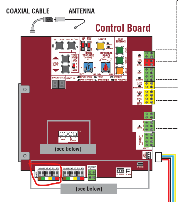
Red to GDO is + on the SBC (top right corner of LA400 board)
White to GDO is - on the SBC
RATGDO Ground on the Dry Contacts side (Under Open and Close) goes to the BOARD Ground (NOT GREEN on the actuator) but the Green wire in the bottom right hand corner of the board that says GROUND.
Now, I got fooled multiple times by loose connections. If the above does not work for you, you should remove the Wire Terminal Block that connects the DC Actuator wires to the board, and re-insert and retighten the screws to hold your jumper wire to the RATGDO.
I’ve got a RATGDO youtube series and will be uploading the video on how to do this as soon as I’ve got it edited
I’m giong to give this a try when it stops raining. I don’t have the LA400. It’s the Liftmaster RSL12UL, which is a sliding gate operator. It has a different main board. But seemingly the same expansion board that supports the SBC function … I think.