That google sheet doc is awesome and it annoys me that I stumbled across this after converting those PDF to excel myself…
But I just wanted to give you a heads up that the linked document you referenced is no longer available on CTCs homepage, but they have a new version instead (to include newer model I guess?), that version also includes a new column “Name” for the functions.
Thank you for this information. Sadly it looks like that this document does not include more registers, or does it?
I have older CTC EcoHeat 7.5 (around 2008-2010), with LCD panel that communicates with main board using rj45 cable and it has unused 4-pin connector behind LCD (see photo). pins are GND, data?,data?, +Vdc (3.3v).
Both data pins measure about 3.3V to GND, but have no idea how to connect it to ESPhome. Is it rs485 or direct UART?
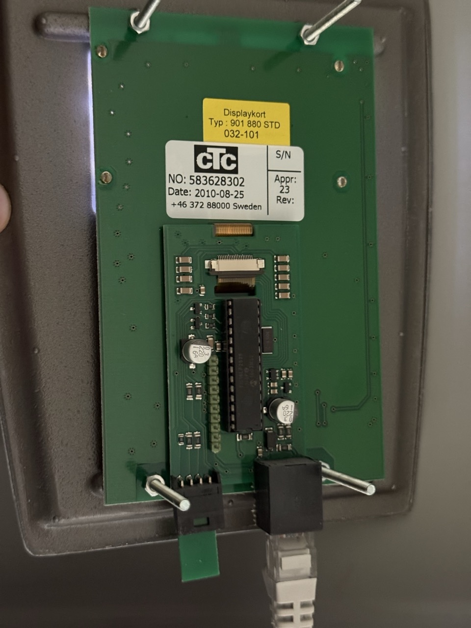
I cannot quite make out the numbers of the chip in your photo, or the pins each circuit trace go to from the connector (you can check with your ohm-meter), but a quick perusal of the IC data aheet will soon clear up the issue. They may be I2C or something similar, or just GPIOs with a bit bang UART, or TTL level or CMOS RS232. It doesn’t look to be RS485 as no surrounding driver chip usually found if there is. You may even find a sample code section in the associated Application Notes that is often followed studiously by the developer that may offer hints for reverse engineering and interfacing. Usually chips of this size are PIC series from Microchip, and they may even be running Arduino code. The board may be an evaluation circuit that has been used as is. If being run from 5v, you may need voltage conversion for ESP chips. If it being used to drive the display, it may have control codes being received as well as data you wish to extract that may need parsing.
What is the LCD display part number it is connected to? This may also assist in identifying the protocol being used, or even to find application notes that may shortcut your research.
Update: have a peek at a similar exercise in reverse engineering at this thread that may inspire your approach.
Good evening all,
It’s been a while since I last posted here but I thought I’d make a shortish post here this evening having spent the last two days going around in circles trying to solve the challenge presented by my ESP32 not wanting to communicate with my CTC GSi12.
I have replaced the original two port display on the heat pump with the three port version. I can report that the RJ12 socket wiring is different between the old and new display. The information posted by kasper-73 previously is likely accurate for the two port display but the three port display is wired as follows:-
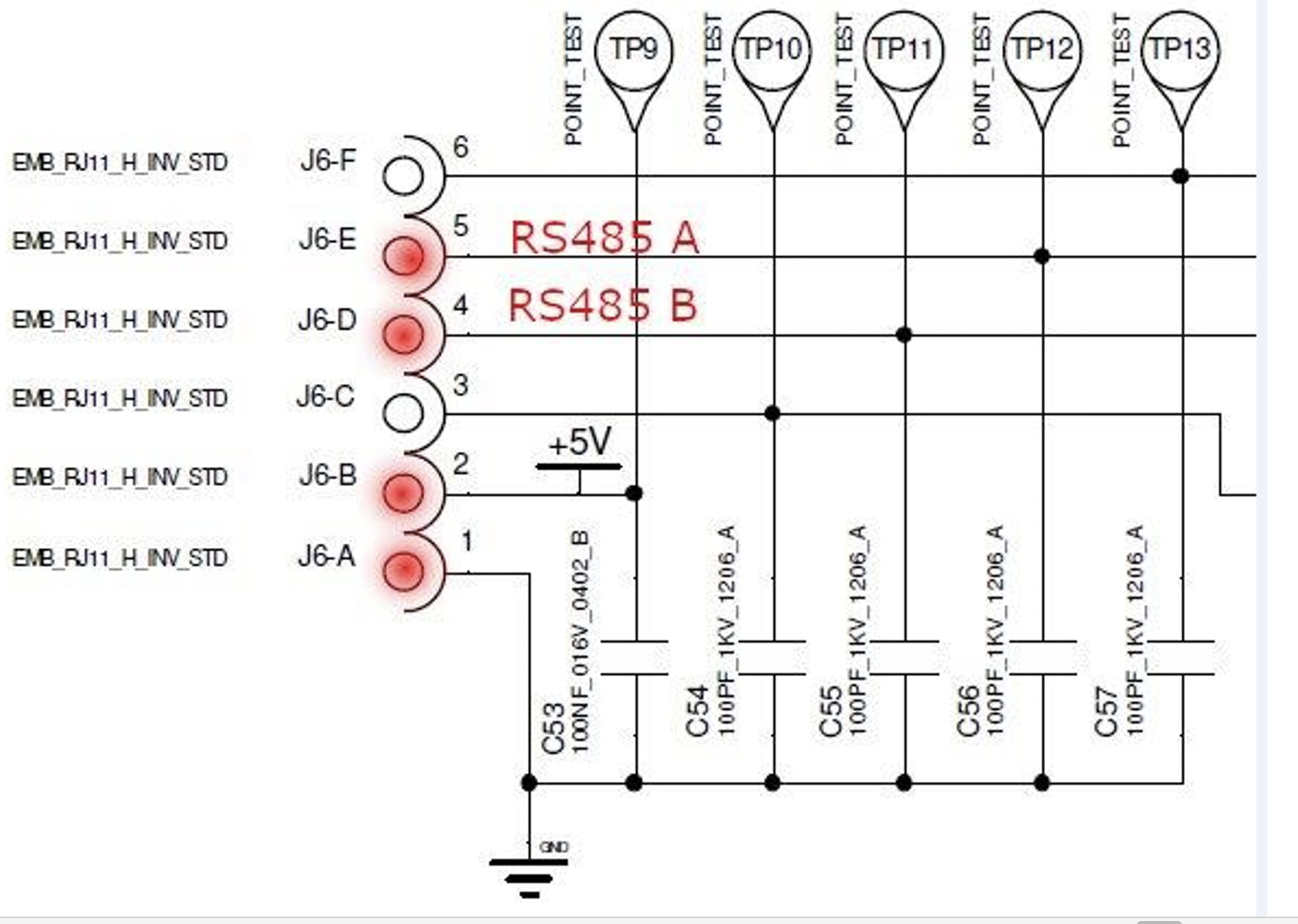
Clearly there’s no flow control pin here so that is a piece of code you can delete.
I had almost resigned myself to buying one of CTC’s £445 devices:-
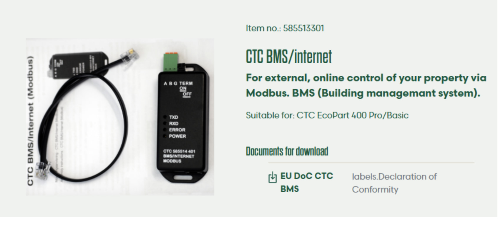
The price is outrageous - it is available elsewhere for some £620+.
Prompted by something suggested to me I dug in my box of RPi bits and dragged out a ‘spare’ Waveshare USB - RS485 bi-directional dongle thing (actually ordered in error as I’d forgotten I had already ordered one)! That one sits between the RPi and the Sunsynk hybrid inverter.
Yesterday I’d only heard and read about ‘Claude’ but have to say I’m something of a convert having seen it do its thing this evening.
The bottom line is that I got the MacBook talking to the dongle and then, in turn, the MacBook talking to the heat pump.
Claude has proposed a new .yaml file to upload to the ESP32 which I’ll try tomorrow.
There will be some tidying up to do but I will publish the .yaml file in full for the benefit of others.
As I type this evening I’m keeping my fingers crossed that the proposed changes will allow the continued use of the ESP32 - right now I’m slightly confused as to how the proposed changes will pan out.
Regards
Richard
Good morning all,
Further investigations, aided by Claude, this morning reveal an ESP32Home device isn’t able to communicate directly with the RS485 signals coming out of the heat pump.
The Waveshare bi-directional USB to RS485 device I was using last night had no issues.
Claude’s initial suggestion was to get a TTL to RS485 adapter but I did a bit of ‘digging’ and found this device which Claude confirmed would do the job all in one.
I’ll update this thread when I’ve tested the device.
Regards
Richard
Good evening all,
I’ve struggled to get the Waveshare device working so ended up utilising TTL - RS486 adapters as per this picture:-

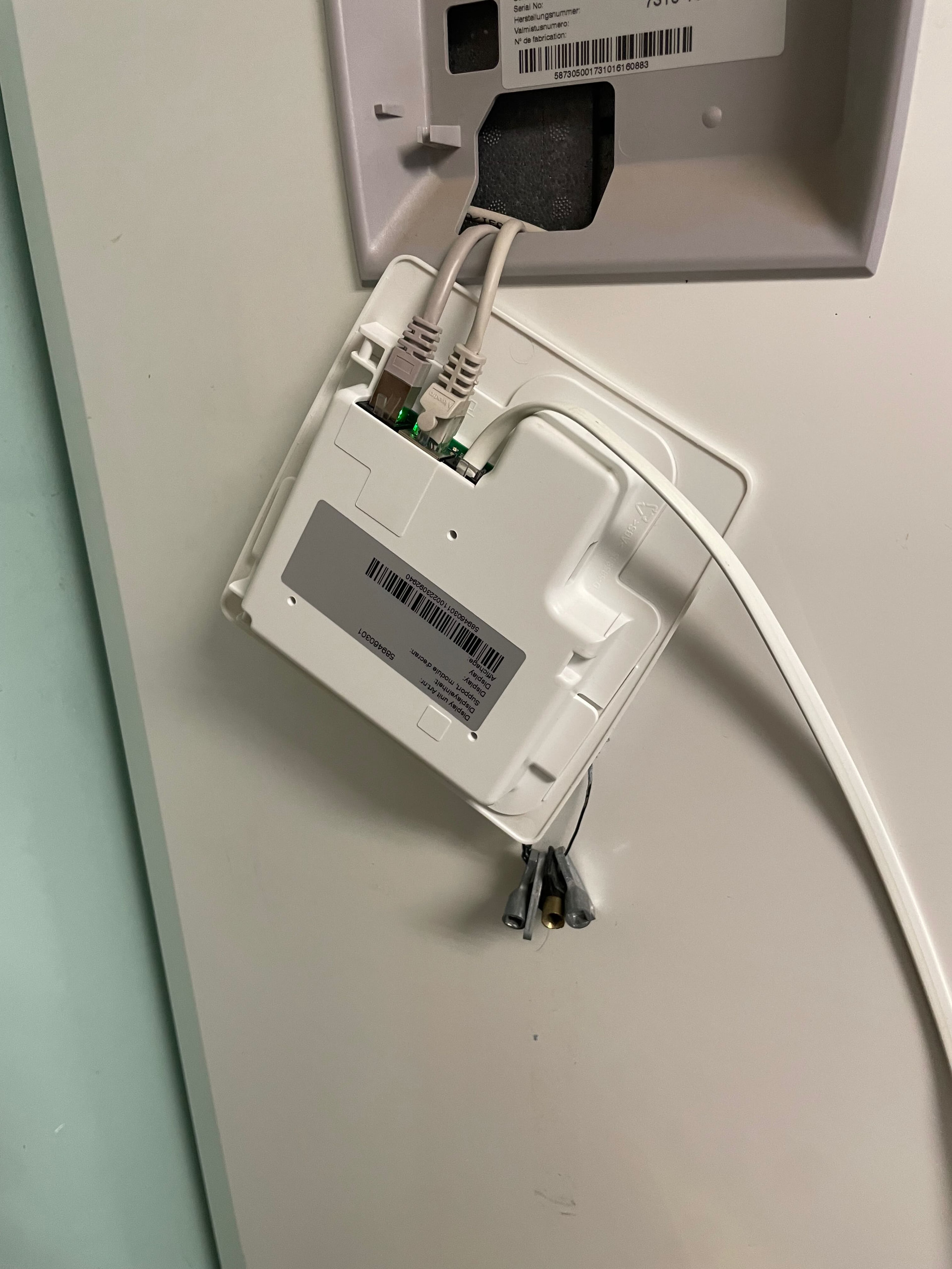
Data uploading to HA:-
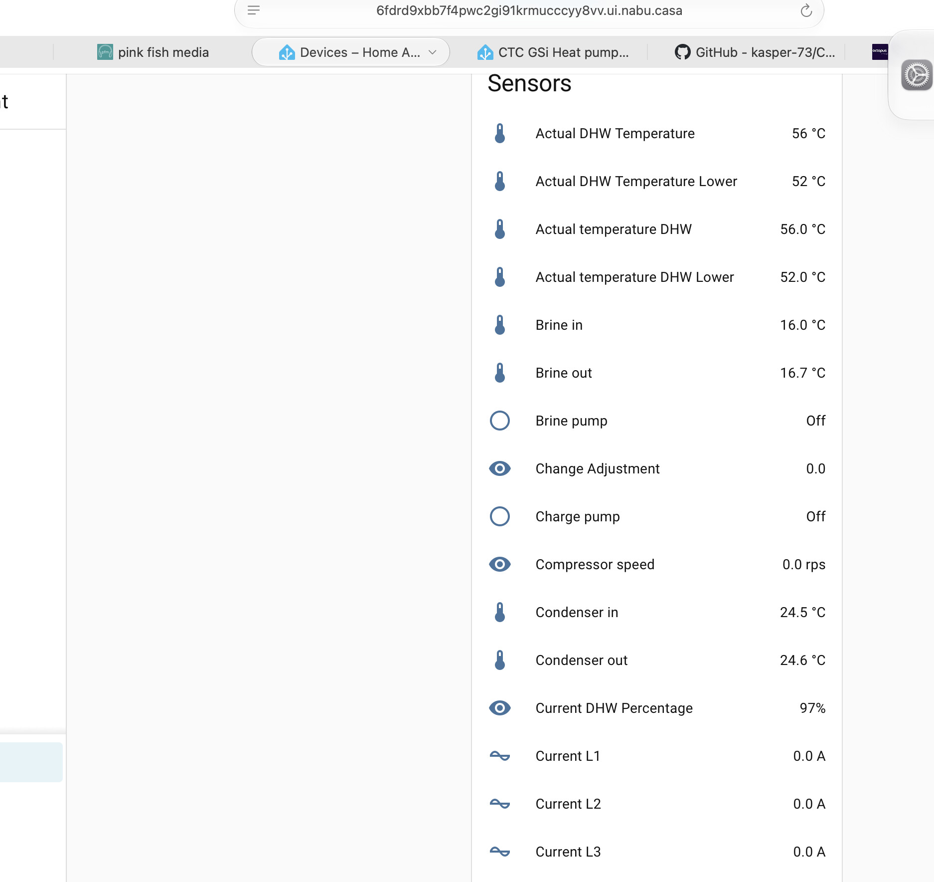
I now need to spend some time getting to the bottom of why I can’t get the Waveshare device working.
Edited bit - After some perseverance I’ve got the Waveshare device up and running:-
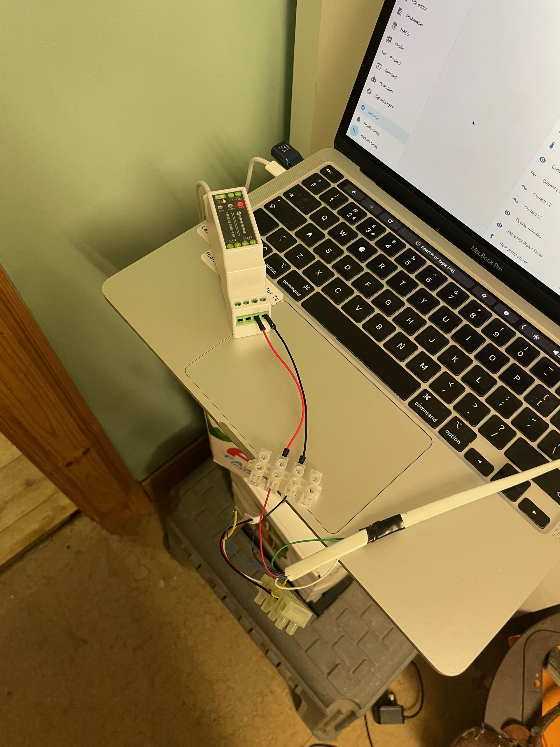
and uploading data to HA:-
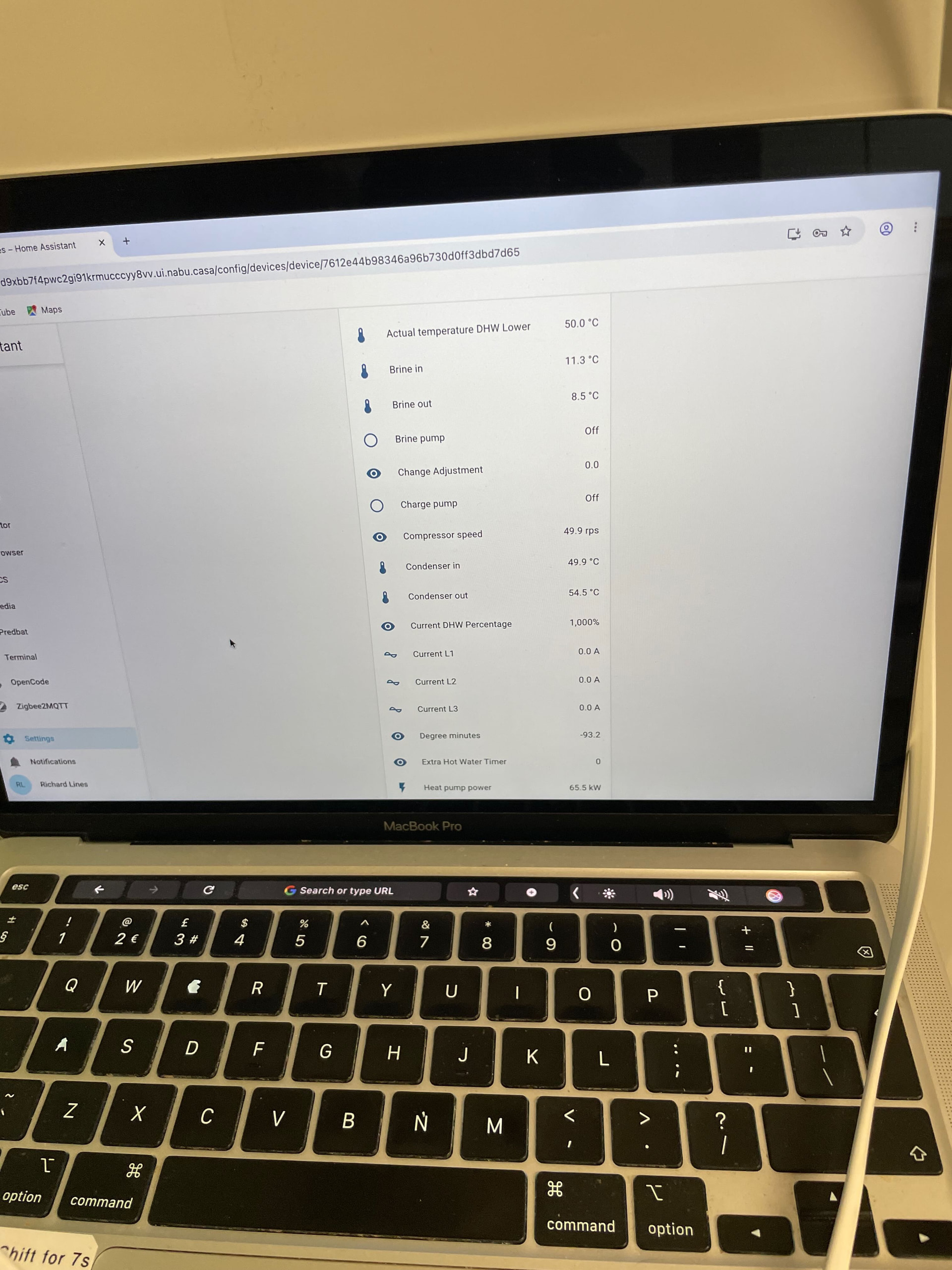
Regards
Richard