Final question I promise - what amperage SSR did you use? I can easily source a 40A one, at 240 V that should be more than enough for a heating coil similar to yours?
My heating coil isn’t actually very powerful. It’s 1100W which comes out to about 9.17A on 120V. I chose the 25A ssr as the cheap Chinese ones are suspected of being overrated.
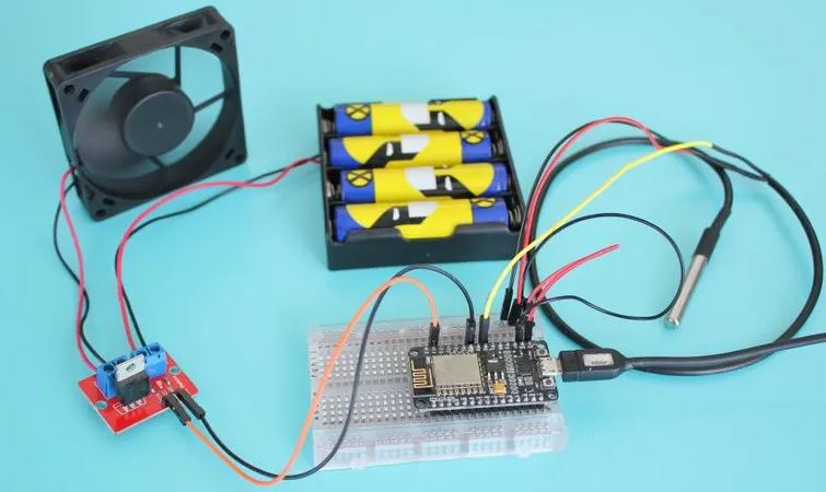
I used a nodeMCU to bring in the sensor signals and for the sensors themselves I used a K-type thermocouple for the smoker box temp and a thermistor probe for the food temp. I only have 1 food probe tho so that’s where this one falls short of the commercial one you are using.
Since the NodeMCU doesn’t use much power I can power it from either a USB wall wart charger or from a USB battery pack. As a test I left it running on a 10,000 mah battery pack and the battery finally died four days later.
The Arduino sketch provides an AP (SmokerConnectAP) on initial power up to enter all of your wifi and MQTT connection settings. Once you connect to the AP then go to IP 192.168.1.4 to enter the config. After you save the settings it reboots and connects to your wifi network and MQTT broker provided. You’ll have to search you network for the new IP address that your router provides the sensor.
If you ever take the box somewhere else you can use it on the new network because if it can’t find the previous wifi network it defaults back to the AP mode and asks for configuration settings again.
the one thing that got too complicated was figuring out a foolproof way of bypassing the need for connecting to an MQTT broker if you go to a place where you just want to use the wifi but not MQTT. So I actually have two sketches - one that uses MQTT and one that doesn’t - so either way it will work. But unfortunately you obviously can’t run both sketches at the same time so if you take it “on the road” you’ll have to re-flash it. I didn’t find it to be worth the time to try to get it to work the way I wanted so I gave up on that part since most people will never use it on anyone else’s network anyway.
Once everything is connected and running the NodeMCU serves up a webpage (that updates every 10 seconds) that I can connect to it’s IP address and view from anywhere on my home network so I’m not limited by range issues of either Bluetooth or RF signals. Both of the ones I had used previously that used RF connections if I got more than about 20ft away it would lose signal.
It also uses MQTT to communicate to HA; again anywhere on the home wifi network.
The waterproof box I used has openings for the USB power connector, the thermistor connector, the thermocouple connector and three status LED’s. The status LEDS show the power on state (green) i.e. if the NodeMCU is powered up, the network connection status (blue) to show that it’s connected to both wifi and MQTT and a flashing activity status (red) to indicate that the program is running and each time it takes a reading it will flash on for 1 second.
Obviously the “waterproof” box isn’t waterproof anymore since I cut all the holes into it but I think it could be made waterproof again by sealing everything up with silicone.
I just now created a github repo to make it easier to download the sketch and the fritzing schematic/wiring diagram.
Here is the parts list along with links to get them on Amazon:
You can likely get them cheaper on someplace like Aliexpress.
The price came out to about $45 total but the initial outlay was more than that since I bought a bunch of the parts above in bulk. But at least now I’ll have plenty of parts for the next project! At least that’s how I justified it to my wife.
The only thing that’s different from that show in the pics is that I ended up moving the USB power connector further into the box and the used a short USB extension cable to connect power. I found that the USB connector board couldn’t handle the stresses from plugging and unplugging the USB cable and it ended up breaking.
This looks REALLY interesting. Thanks for your work on this. I’m looking to do something along these lines for my kamado charcoal smoker. Does anyone have any ideas on how to modify this to control a 5v or 12v DC fan rather than the 120v AC heating element?
You could most likely just replace the slow PWM output component with either the ESP32 LEDC component or ESP8266 software PWM component depending on your microcontroller. That specified output pin would then control a mosfet or other suitable transistor that would switch the 12v or 5v supply to the fan at a high frequency while modulating the pulse width to vary the amount of power delivered to the fan.
I am a little confused. Did you connect the thermocouple probe to the Max31855 and the thermister probe to the MAX6675? On the pictures I only see the Max31855. Any reason why you used a MAX6675 and a Max31855 instead of two of the same? Thanks for your post and for sharing your project!
It seems that he is using a MAX6675 in his project. The MAX6675 is obsolete and the MAX31855 would be a suitable and better alternative. They are both thermocouple amplifiers. You only need one of these chips per thermocouple used.
For the thermistor, it is used as one of the resistors in a voltage divider so that you can read the voltage across the thermistor as it will change in relation to the temperature.
I originally ordered the MAX6675 but the right angled pins on the pre-soldered board didn’t allow me to fit it in the box. And when I tried to de-solder the pins to replace them with straight pins I screwed up the traces. So the only boards I could find that didn’t come pre-assembled with 90 degree pins were the MAX31855 boards so I ordered those instead.
I’m really not sure if the MAX31855 is that much better than the MAX6675 for use in this case but that’s the one I ended up using.
And as @mcarter14777 said above, you only need one of those for the thermocouple for the smoker box temp. the thermistor just gets connected directly to the analog input pin thru the voltage divider circuit.
Be aware that not all thermistors are the same. there are 10K, 100K and 1M thermistors and can be negative co-efficient (NTC) and positive co-efficient (tho I’ve never seen any of those only the negative co-efficient ones).
I tried the 1M thermistor and never got it to work and couldn’t find a 10K thermistor so I used the 100K thermistor along with a 99K voltage divider resistor (I just noticed I still have the 1M voltage divider resistor in the schematic).
I am working on a version that uses charcoal and not electricity. I am adding a fan to try to control the temperature. But at this point I am just prototyping as I am waiting for a thermistor to arrive from China.
To control the 12v fan I am using an IRF520 mosfet like this one.
You connect the fan and power like below. The signal pin from the mosfet to a gpio pin on the microcontroller and the ground pin to ground on the microcontroller. In the esphome code just create a gpio switch.
Hey atomicpapa, I found this thread because I wanted to do the same thing to my Masterbuilt smoker. Mine has the same control as yours. Right now I have a more primitive (not connected to home-assistant) controller I built about a decade ago that uses an industrial PID controller rather than an ESP. It’s as simple as cranking the masterbuilt’s knob to max and then plugging it into the other controller.
I am trying to do something similar but I want to actually control the smoker. I am presently controlling it with this thing: https://youtu.be/2qsO83_x_7U?t=91
I want to convert the controller to an esp32 so that I can use Hassio…
@mcarter14777 thanks for this project, my wife is the smoker and she has a very simple cooker but with good results and complains about all the problems mentioned above so I think this would be awsome for me to build for her. I have put together a BOM does this look ok?
Bill of Materials
• SSR-40DA solid state relay
• ESP32 wroom dev board or similar
• ADS1115 Module ADC - 4 channels
• Thermoworks - High Temp Air Probe with Grate Clip x1
• ThermoWorks - High Temp Straight Penetration Meat Probe (up to 3 probes)
• 1/8 jacks (3.5mm) Mono x4
• 110v to 3v power supply
• Heavy duty 3 prong AC outlet & inlet
With regards to the PID control; can anyone get me any tips for manual PWM control? I am using the PID control to control home brewing equipment. For some of the process I need the temperature control that the PID provides but there are other parts of the process that I simply need to set the PWM to 50% for example.