Has anyone managed to integrate a DSC neo panel? It’s not a very “new” panel anymore. I’m surprised I can’t find anything on it…
Nobody has this panel?
DSC uses a proprietary bus and protocol for the Power Neo series. I have yet to see anyone or any product that integrates with it.
I sold my Neo and bought an old school Power Series. Just installed the panel tonight, and my EVL4 will be here next week.
DSC opened it up to control4, so it’s possible, but haven’t seen anything else.
I just found for Indigo Domotics, not HA
Unfortunately, this is for PowerSeries, not Neo.
Hi.
Just wondering if you found anything on DSC Neo and anyway to communicate with it?
Not directly, no. I able to arm/disarm through my alarm.com service and the response time is pretty quick. Unfortunate since DSC does offer local integration for select integrations like control4.
Hi guys,
I happen to own DSC Neo alarm system with TL280 that got useless after DSC killed their PowerSeries Neo Go App.
I managed to get basic understanding of the ITv2 protocol by reverse engineering it. I documented it and developed a minimal integration client that behaves like TL280. See GitHub - rmilecki/dsc-itv2-protocol: DSC ITv2 protocol .
The problem is that ITv2 switches to encrypted communication after exchanging few initial packets. It’s probably AES but:
- I don’t know how to obtain encryption key
- I don’t understand syntax of packet TL280 sends to integration server for starting encryption
Is there anyone around who is capable of debugging it further and would like to help & contribute?
If we could understand how ITv2 initializes encryption I think we could develop open source integration support.
Hi Rafał,
I just wanted to remark, that if you are located outside of US TL280 is not “completely” useless - you can use their ConnectAlarm Android/iOS app for self monitoring.
Regards
I have an idea that in theory would take remote control of one of the more simple physical neo keypads. Specifically, take control of the two components that need to interact with humans in an unencrypted form: the display, and the keypads pushbuttons. Kind of like having your own personal robot standing at a physical keypad reading the display out to you and pushing buttons you ask it to, but done electronically.
To get the panel status, my idea is to sniff the data the keypad sends to its own 16x2 lcd screen. It is likely a standard 16x2 display and a lot of 16x2 lcd displays have a simple 8 bit data bus used for displaying the characters on the screen (some have a 4 bit mode). If you could intercept this signal with a microcontroller you could read the keypads display remotely, know the panels status, and design an virtual keypad display in software that mirrors the physical keypad.
The second part would be to “push” the buttons on the keypad electronically. My guess is that each button you need to push will have to be soldered and wired to a GPIO on the microcontroller to mimmick it physically being pushed. It may require dry contact relays to complete the circuit but pulling one side of the button high/low may also trigger the “push”. There are 25 buttons on the full message keypad.
With all of this combined you should be able to create a virtual keypad in software or home assistant that controls the physical keypad wired to the panel.
Here is a good video on how the data bus works on a simple 16x2 lcd display:
Here is another video of someone sniffing the data bus on an old calculators lcd:
Update on the Keypad LCD sniffer:
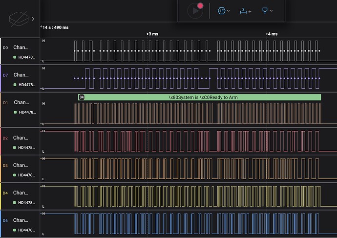
I was able to decode the lcd display on a full message keypad by soldering wires to the lcd data lines. It uses a HD44780 protocol in 4 bit mode. Therefore to interface the complete lcd you need E, RW, RS, DB4, DB5, DB6, DB7. However since I am not concerned about when the keypad is reading or attempting to read from the lcds ddram yet, R/W can be ignored. I originally thought of using the R/W pin to actively read the ddram but my concern would be if you read at the same time the keypad wrote there would be a conflict or you would miss the data. If the keypad makes use of the busy flag to check before it writes it could still be possible, but for now its safer to just passively sniff the data.
This is what the signal looks like under a logic analyzer. You can see the built in HD44780 decoder, is reading “\x80System is \xC0Ready to Arm”. RW = white, RS = purple, E = brown, DB4-7 = red/orange/yellow/blue. The \x80 and \xC0 codes are likely internal register instructions to clear the screen and drop to the next line as the RS line is low when that data is written.
I then modifed some HD44780 decoder code in Arduino IDE to have an ESP32 sniff the data and print it to the Serial Output.
Here is two outputs from my ESP32 showing Ready to Arm and a Zone fault by opening the deck door.
Getting the data into Home Assistant is the next task to figure out, but at least this shows you can remotely access the keypad display’s information to create a virtual display in software.
Here is another screenshot of my serial monitor after adding a bit of code to format the output to mimmick a 16x2 display.
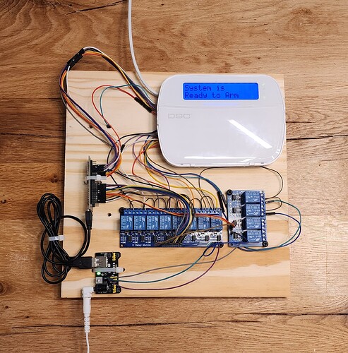
Here is the final neo keypad integration in all its ridiculous glory. For pushing the buttons I originally used 10 relays in an array of 5x5, joined at common, so when the coordinates of any two relays are called, the corresponding two points on the keypad’s button matrix are connected pushing the intersecting button. For example, X1,Y1 pushes 1, X2Y2 pushes 5, etc. My button pushing function also takes a delay variable so you can control the length of the push, for example, holding down the function buttons for arming etc. I am controlling all 25 buttons with 10 gpio pins.
I then created a compact pcb using optocouplers that the esp32 devkit plugs into that reduces everything down to a very practical size (see the update below).
Mqqt is used to communicate between the controller and Home Assistant to update the virtual lcd status and tell the controller what buttons to push.
You can also use the keypads auto scroll faulted zones function to trigger input booleans and sensors in home assistant for each zone when the corresponding zone fault displays on the lcd. The zone can be reset when “System is Ready to Arm” is re-displayed, or if there are multiple zone faults, after a certain time period passes without the zone re-appearing in the scrolling list as one of the faults.
The original prototype using relays:
Update on Jan. 1, 2024:
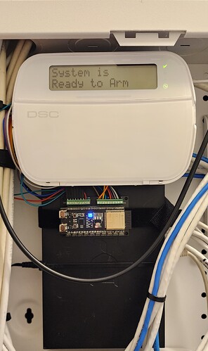
I have now designed a compact pcb that uses an array of optocouplers instead of relays and has female headers to plug the ESP-32-S3-Devkit-C1 into it. It reduces everything down to a size just a little larger than the esp32s3 dev board. Also without the 5V relays the entire board can run off the keypads 3.3V and no longer needs any external power supply. The LEDs indicate which optocoupler coordinates are called when you push the buttons on the virtual keypad. I also made a slightly smaller version with the LEDs removed.
My new compact pcb with esp32s3 devkit:
The new setup next to the keypad and installed in a network cabinet.
The Home Assistant virtual keypad:
I now have a fully functional virtual keypad in Home Assistant and can monitor my zones and integrate with other automations. For the keypad I simply used a markdown box for the lcd message and a grid of buttons for the keypad buttons. The virtual keypad is very responsive and works just like a physical keypad. I also got Home Assistant’s Alarm Panel template working with the integration as well, but I find the virtual keypad much more functional.
Have you seen this Kantech integration with the Neo?
It uses the TL280. It shows programming addresses for the inbound/outbound encryption keys in the Neo panel. I wonder if this could be the key no pun intended. lol
Hi, please also have a look at Cathexis integration:
Page 12, relies on same inbound and outbound encryption keys to establish a local integration with their NVR.
Another available integration:
Hey, your project is very gap filling. Can you share some documentations or codes?
Great job! I’m also interested about more details - pcb schema, code and how its connected to keyboard. Can you post more details?
Added more details on main probject page at DSC Neo Alarm Integration for Home Assistant | Hackaday.io under “instructions”.
Added connection diagrams, wiring schematic, ESP32 code, and home assistant code to the main project page under the instruction page.


