- Preface
- Device Introduction
- Integrating with Home Assistant
- Adjust the power output in real-time based on grid power
- The API of the Wi-Fi SCR module
- Reference
Preface
This document will demonstrate a method for linearly controlling the power output of the resistive load(such as the heater in the boiler tank) in the home assistant.

If you have both a solar PV system and a resistive load, you can save even more money by using this method. By reducing or shutting off the load power when the system draws energy from the grid and increasing the load power when energy is being exported to the grid, you would manage costs effectively. This strategy ensures that more of the energy generated by the solar system is utilized on-site, reducing the amount exported to the grid (More self-use rate).
Device Introduction
The SCR module, as shown below, controls output through voltage adjustment and can manage up to 4 kW of resistive load.

We have incorporated an ESP32 as the control chip inside the SCR module.
To simplify testing, we have not independently developed firmware for the ESP32 but instead used the firmware from ESPHome.
The related configuration file is as follows: scr-485.yaml

Integrating with Home Assistant
The experiment includes the following devices:
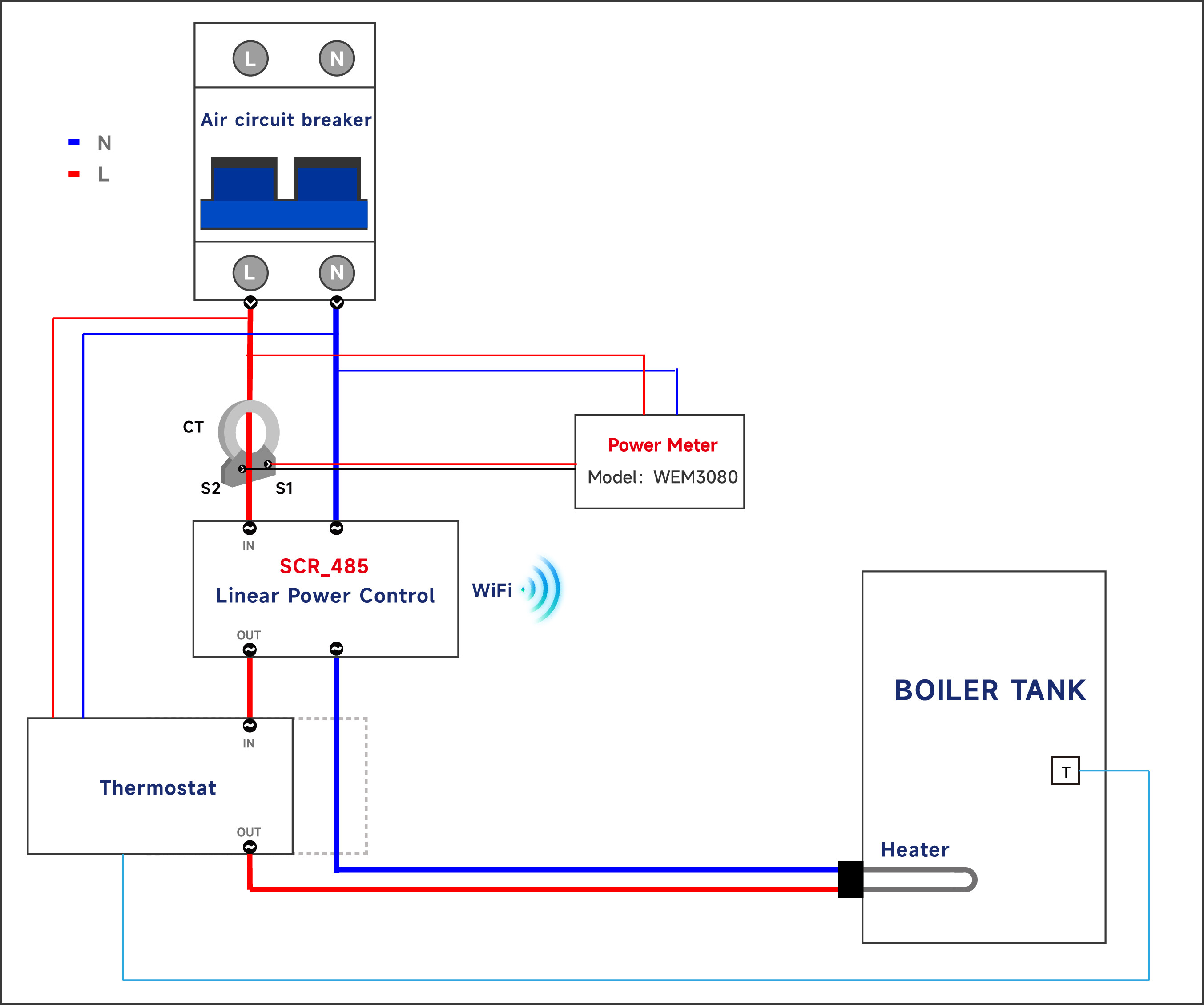
- Power Meter: Uses IAMMETER’s single-phase electric meter WEM3080 to measure the actual output power of the SCR module. Other HA-compatible meters can also be used as substitutes.
- SCR_485: An SCR module with “Linear Power Control” and integrated Wi-Fi (ESP32) capability, allowing for linear power adjustment via Wi-Fi.
- Electric kettle: Used to simulate a heater within a boiler.

The wiring diagram for the experiment is shown below (for simplicity, no thermostat was used in the experiment. If controlling a boiler heater directly with the SCR module, a thermostat could be introduced between the SCR module and the heater).
Configure “SCR_485” Wi-Fi Credentials
The first step of the experiment is to configure the SCR module’s Wi-Fi to connect to the local network.
Since we are using ESPHome firmware, configure the device to connect to the local network via Wi-Fi according to the features provided by ESPHome.
Connect to AP Scr-485 and open 192.168.4.1 in the browser
Enter your router’s SSID and password

Add Device
The first experimental step is to add a device running ESPHome firmware to Home Assistant.
Settings → Devices & Services

Discovered → “scr_485” CONFIGURE

Click “SUBMIT”.

Click “FINISH”

ESPHome → DEVICE


Controls & Sensors: Click “add to Dashboard”

Configure the Dashboard (optional)
Display both the power meter and “SCR_485” on the Dashboard, adjusting the display to your preference.
If a WEM3080 is not available, other meters can be used as substitutes.

Set Max Power
Now you can try to control the output power of the SCR module.
First, set the SCR’s “Max Power” to 1500 W.
After this configuration, the maximum power setting will be limited to 1500W. Any attempt to set the power value above 1500W will not be effective.

Control Power
Set the power to 500 W.
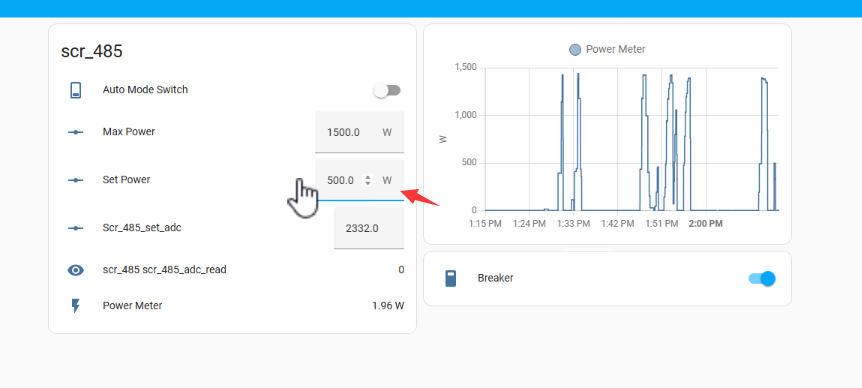
Then you will find the reading of the “power meter” is around 497 W.

Set the power value to 1300 W and the reading of the power meter is around 1347 W.

Please note that the actual power output may not exactly match the set value. But the difference is little. This discrepancy occurs because power control is governed by voltage regulation. While calculations of the output voltage assume a fixed supply voltage (e.g., 220V), in reality, the supply voltage varies continuously.
Adjust the power output in real-time based on grid power
In this chapter, we will outline an automation strategy in Home Assistant (HA) designed to achieve the following objectives:
- Reduce the load power when the power exported to the grid decreases.
- Turn off the load when there is no power being exported to the grid.
- Increase the load power when the power exported to the grid increases.
More details will present in the next tutorial.
The API of the Wi-Fi SCR module
Since the WiFi module runs the ESPHome firmware, these APIs are supported directly.
1. GET number/max_power
Set the maximum power of your boiler
Request URL: http://{{IP}}/number/max_power
Method: get
Successful return example
{
  "id": "number-max_power",
  "value": "3000",
  "state": "3000 W"
}
2. GET number/set_power
Set the output power
Request URL: http://{{IP}}/number/set_power
Method: get
Successful return example
{
  "id": "number-set_power",
  "value": "500",
  "state": "500 W"
}
3. Set number/max_power/set
Set The maximum power of your boiler
Request URL: http://{{IP}}/number/max_power/set
Method: post/get
Example: http://{{IP}}/number/max_power/set?value=1500
Successful return example
Status: 200 OK
4. Set number/set_power/set
Set the output power
Request URL: http://{{IP}}/number/set_power/set
Method: post/get
Example: http://{{IP}}/number/set_power/set?value=500
Successful return example
Status: 200 OK
5. Switch/auto_mode_switch/{turn_on/turn_off}
Select automatic/manual mode
Request URL: http://{{IP}}/switch/auto_mode_switch/turn_on
Method: post/get
Successful return example
Status: 200 OK
Remark
More API references: Web Server API - ESPHome - Smart Home Made Simple
Reference
We have always been committed to finding ways to dynamically adjust load power to improve the self-use rate of solar PV systems. Some of these methods include:
Controlling the on/off status of sockets based on grid power in HA
Managing the EV charger through OCPP to achieve a higher self-use rate in the solar PV system
Control the EV charging power with regard to the solar PV output and grid power reading in HA
Monitor your solar PV system in Home Assistant
Four ways to integrate the Electricity Usage Monitor (IAMMETER) into the home assistant

