@PipeDeveloper yes, this should work - that’s what I did! @Dilbert66 has done an amazing job on this project - I can’t thank him enough!
I set this up last night and the example YAML works perfectly (just delete away zones you don’t need).
I’m now working on how to enable the control of my alarm system via an “Alarm Panel”. I’m working through the GitHub example “Sample Home Assistant Template Alarm Control Panel configuration with simple services (defaults to partition 1)” and I will post back when I figure out how to get this going (maybe I can contribute some more steps to the guide when I succeed with it).
You can place it anywhere you want under the esphome directory. If you use a different path you would then need to change the yaml include accordingly
includes:
- dscKeybusInterface/
I’m planning to add zone extender emulation to the program once I receive my emulator board and decode the protocol. This way, your esp8266 would also be able to add more hardware zones to your system.
I have done that with my corresponding Honeywell/Ademco Vista esphome custom component. I’m still finalizing some details but will publish that soon. It also uses an esp8266 to interface with the Honeywell system for full control.
I made a mistake with my replacement variables… Without realizing, I was hard coding my node name vs using the variable systemName. To avoid this, create the new node with the system name you want to use. systemName must equal the node name.
I learned how to go into Developer Tools / Services (never had to use services before). I can arm the alarm by calling the services using this interface.
*Making progress with the “Alarm Panel” GUI. Still learning more from the example “Sample Home Assistant Template Alarm Control Panel”
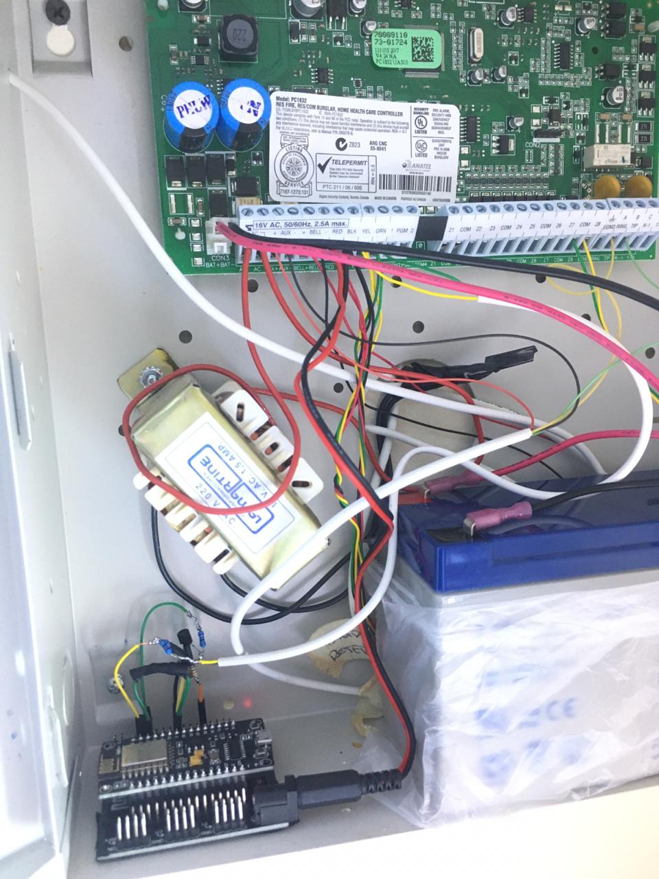
Finally i did some wiring and i implement it. I leave some pictures.
I dont know if pull up resistor values is necessary to use 10k, 15k or 33k, but its hard to get electronics components on my location, but it seems to works fine, zones are detected fine.
Finally i used four resistance of 15k ohm, one resistance of 1k ohm and one 2N2222A transistor, And looks like this.
I think i should call ADT and ask if they got any documentation. Also i can see that my system got some issues of some sensors, low battery and RF retain (like if i open a windows, it says “open”, then i close the windows but it still says “open”, i checked on the KeyPad and it says “open”, so thats means that RF module retained the signal, and something happen on the sensor, low battery, wherever)
I see that this library is pretty solid and issues are related to my system hardware, so i will take some advantages during my contract with ADT to fix all issues before leave the service.
Thank you very much @Dilbert66, your work is awesome, and @generic for your comments.
Glad it works for you! As to the resistors. It is absolutely necessary to have voltage divider setup with a simalar ratio as this drops the 12 volt down to a safer value below 3.3 volts so you won’t fry your chip but the actual values are not critical, you can use whatever you have as long as you keep it at a few thousand ohms . You don’t want to go too low or you will pull too much current from the panel bus
I’ve also got most of the zone expander working in my dev branch. Testing with different versions of DSC panels right now. With this change you will also be able to set up the esp8266 as a pc5108 and add multiple virtual zones to your panel. What that means is that you will be able to use any home assistant sensor/switch to act as a zone on your panel.
I have also added relay module emulation so that you can do the reverse and have your panel control things on your home assistant instance.
Ok, yeah as i said it’s just temporal, i’ll change it in the future to the correct values.
Also I have found missing zones. I didn´t know but there is a hidden reed switch on the back of the siren outside. And one hidden magnetic on a old wardrobe i think for a safe-deposit box but we never ever got one hahaha.
Just one more question about the pannel and maybe would help to make a complete app for home assistant.
1.- In the beggining i described my system as wireless RF. It works pretty nice, no matter they are wired or wireless sensors, all zones are detected fine. There is something aditional that would help to have more safety systems, about the battery status of all wireless sensors (if it applies, obviusly)
This will help to know if there are RF sensors that are having issues, and let you know when you should change batteries.
If you press # on the keypad it shows all sensors with “low battery” i don’t know if there is more specific information, like voltage or “%”, but it’s ok, any kind of this information will help anyways. Specially for people that got IR sensors that are wireless, that’s more common to see.
2.- This is just a home assistant side, for lovelance, i would like to have a good card to access services like arm, disarm, stay_home. Like buttons and info entities.
Good idea about the ir battery and other statuses. I will look into that. The panel will see all messages from the rf devices so I’m sure its there. I just need to provide a field on esphome to format and display it.
I’ve pushed a test version to the “dev” branch at https://github.com/Dilbert66/esphome-dsckeybus/tree/dev that includes full pc5108 zone expander emulation. I’ve tested on my own systems and works well so far. Needs more testing on other systems. The current zone max is set at 32.
The expander module will not be supervised by default as it’s not needed for operation. To use it’s just a matter setting expanderAddr1 and 2 to one of the range address you want.
  #zone expander addresses:
  # 9  - zones 9-16
  # 10 - zones 17-24
  # 11 - zones 25-32
  # 12 - zones 33-40 (for systems with 64 zone support)
  # 13 - zones 41-48 (for systems with 64 zone support)
  # 14 - zones 49-56 (for systems with 64 zone support)
  # 16 - zones 57-64 (for systems with 64 zone support)
  expanderAddr1: "0" # 1st zone expander emulator address to use . Set to 0 to disable.
  expanderAddr2: "0" # 2nd expander emulator address to use . Set to 0 to disable.
A new service is also made available in home assistant called esphome._set_zone_fault with attributes zone and fault:
zone is 2 digit zone number and fault is 0 or 1 where 1 sets a zone as open and 0 closes it. By calling this service from a home assistant function, you can enable any event, sensor, etc to trigger any one of your emulated zones in your alarm system.
Relay module support is also added. This will give your panel the ability to trigger an event on any PGM channel output. See the yaml file for an example configuration. An example output for pgm 1 will show in home assistant as PGM 1. You can add more fields in the yaml config file.
This version now also adds the ability to display the low battery warning status of any wireless zones. These will be showing in the “zone status” field of the yaml. Also in that field, you will see the alarm status of any triggered zones.
The display format for a low battery is BL:zz and alarm status will be shown as AL:zz where zz is the zone number. Note that this won’t capture already existing low battery warnings as it depends on the pc5132 module status update command which only sends on status changes.
I just want to say thank you to @Dilbert66 for putting in the work for this and all the supporting projects that has contributed.
I was able to successfully install this on my PC1864 yesterday and am very happy with it so far. As a bonus I can control the alarm through HomeKit using the bridge plugin.
I am trying to have HA send me an alert if the system is in alarm. Can anyone provide some guidance on this? Do I need to set up an automation so that the notification will be sent or is that automatic with and Alarm Panel in HA?
If I have to setup an automation, will it be comparing the petition status with “In Alarm” to trigger the automation?
Hello @Molot
If you want to use ESPhome with DSC Alarm library, please follow the steps on the repository.
Actually you may use 10k and 15k resistor and it will work, but its not correctly use those values.
Have in mind that those resistors acts as a “voltage divider” and not as “pull down”, because they are digital signals with a specific voltage 12v on DSC and 3.3v on the ESP8266.
The input is arround 12.3 - 13.7v provided by the DSC pannel. So if you use 15 and 10kohm, the output will be arround 5v, which is fine for arduino and most of popular boards, but for ESP8266 its not ideal. NodeMCU and WemosD1 can tolerate 5v tension on digital pins and thats why it will work but i repeat its not correctly.
My recomendation, follow the first link with the full guide documentation and schematics. Use 33k and 10kohm in stead, that will drop to 2.7 - 3.3v and it will work fine also.
Both will work but when you use the correct values, you save energy, stability and feel sure that you did a good job using the correct values.