I know I already asked you this but can’t find your reply in this pretty long thread. Can you give me some 1-2-3 steps on how to create an automation to send a notification when the alarm is triggered? Not sure which event to use. Thanks.
Just look at the partition alarm status. al_1 or al_2 where 1 and 2 are the partitions. You can also look at the event status. “evt” sensor. As to creating an automation, just read up on home assistant automations using those sensor values.
@wkchick @Dilbert66 Believe it or not but I was able to read the status and you cant imagine how I feel right now ![]() I could not have done it without your help.
I could not have done it without your help.
I first installed ESPhome on homeassistant and modified a couple of things in your yaml file and tried to compile and upload it and it compiled successfully, and next I started attempting to wire things. I had a kit of various resistors but I did not exactly have a 33k ohms, so what I did was use the closest one to that which was 47k ohms instead (which I had). So I am not sure if that is acceptable or not ![]() I also had a 10k ohm so that remained the same.
I also had a 10k ohm so that remained the same.
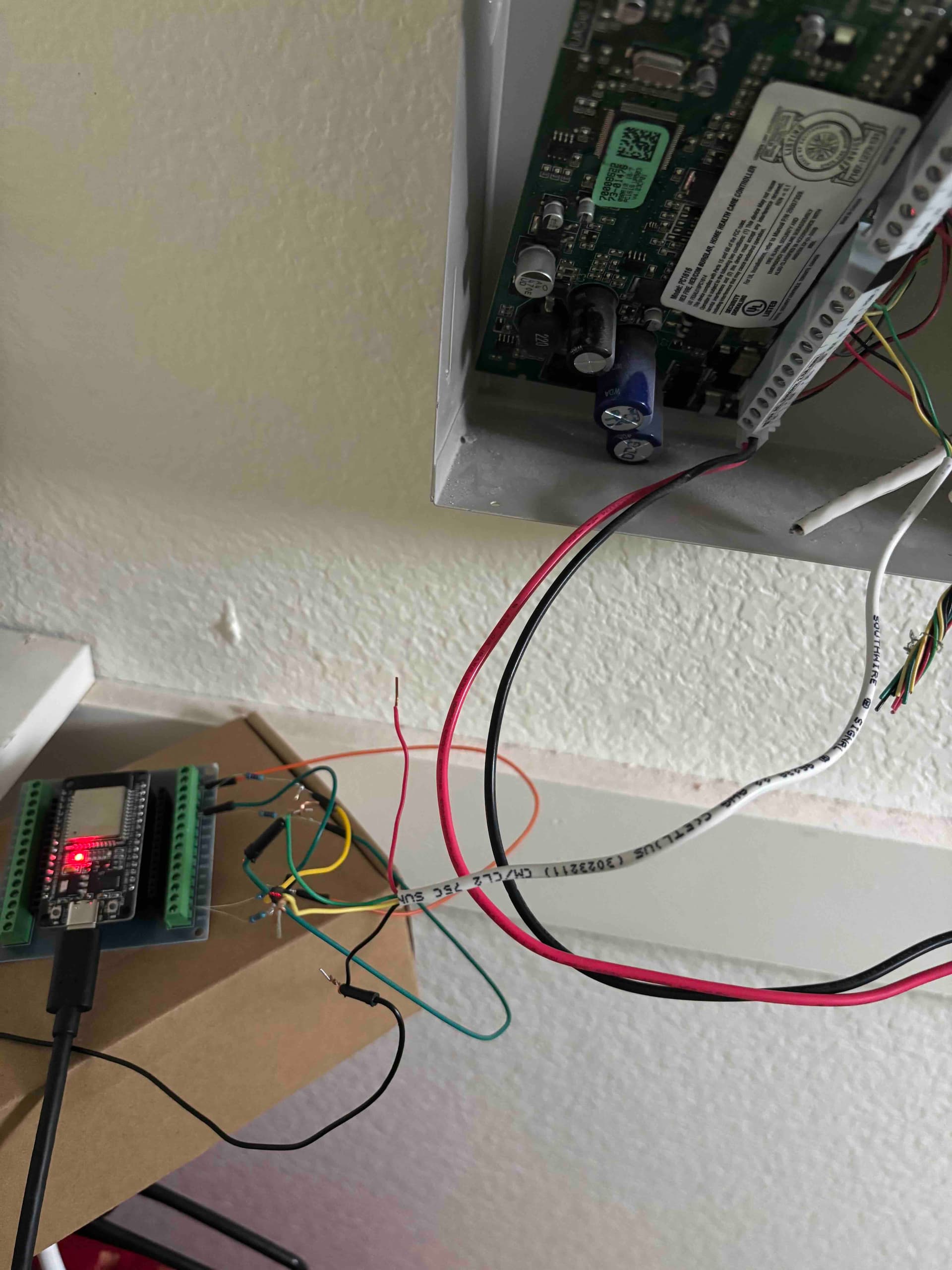
My wiring looks horrible and I didnt solder anything. I also dont know if this is the right away to connect things but as a newbie, I did my best from what I thought it ought to be. The resistor wires were so tiny, I had a hard time getting them to stay in the screw terminal ![]() .
.
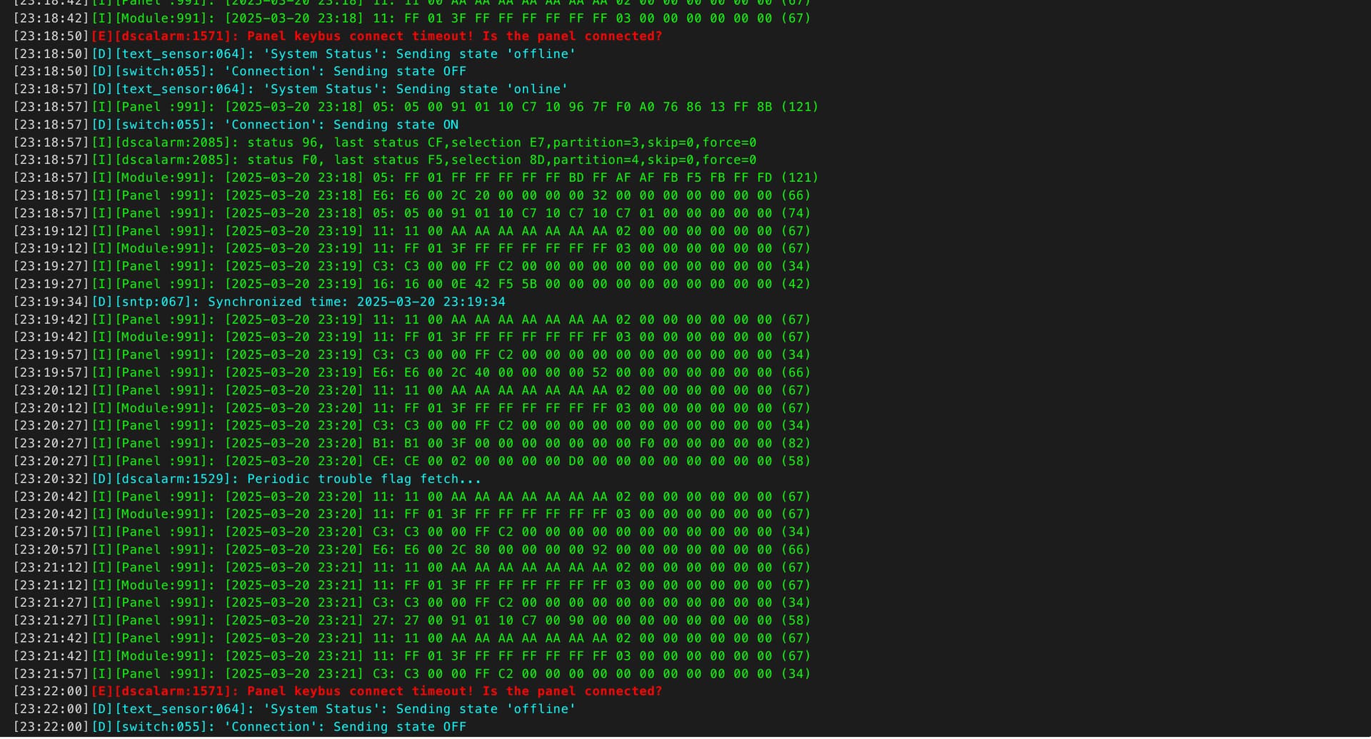
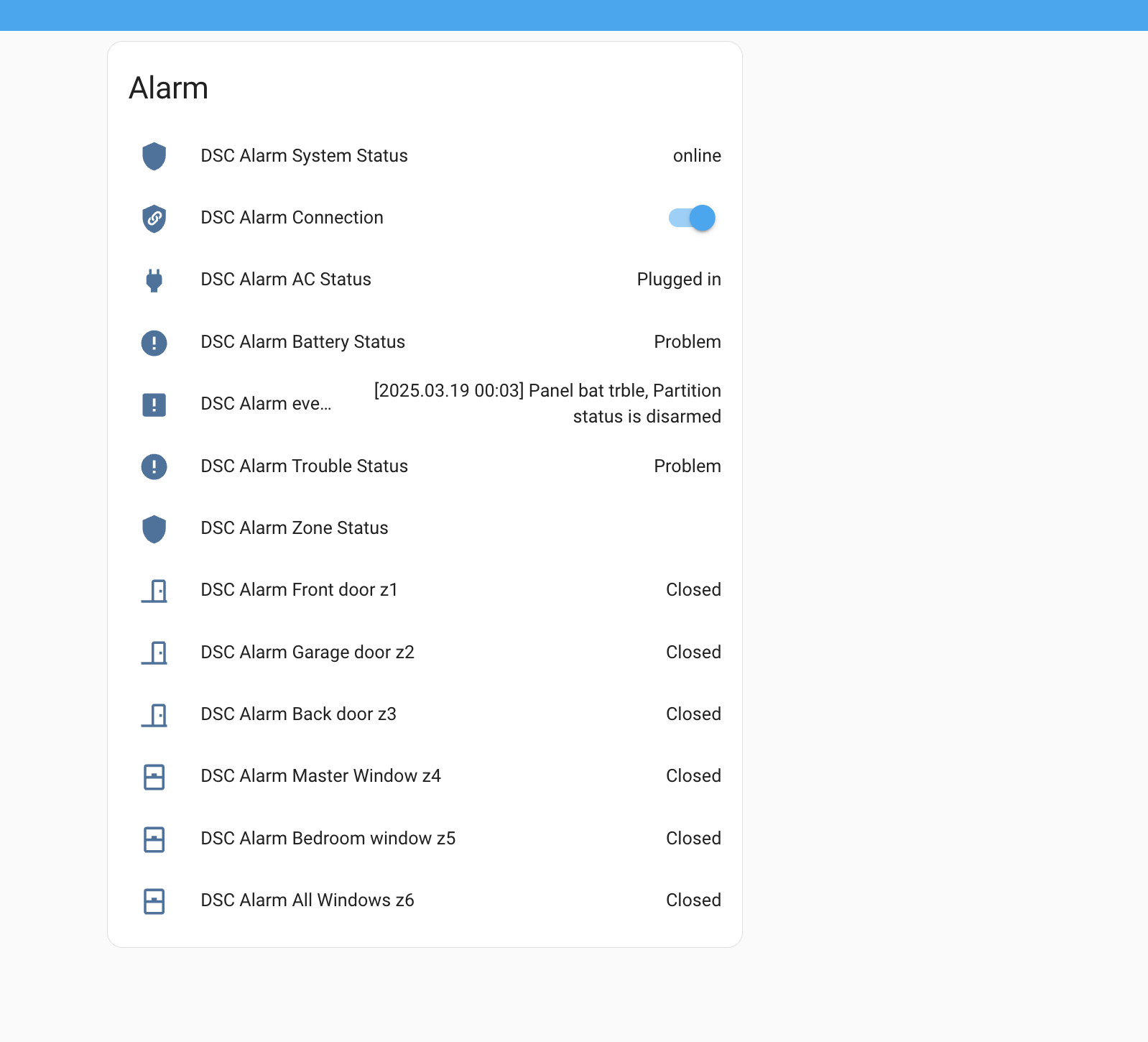
Anyhow, I noticed in the logs, that it looked like it restarts randomly, could you please check if that is the case (I attached a screenshot)? Also I saw some warning about some trouble with the battery? what is that about? Is it the battery for the DSC panel (if so where is that) ? or something else?
I tested opening and closing the doors/windows and it was instantly shown in home assistant!
And now that I am able to read and get the status, I would like to get this wiring done a bit better, maybe I can get a board printed that already has the resistors built into it? Is that possible? I know nothing about doing PCB design or ordering them, or what websites to use etc. so any ideas about that would be helpful.
I appreciate your help and I am so grateful for this project. I am getting to learn so much.
The error in red indicates that the ESP is losing the connection to the panel most likely due to a bad or loose connection on your wiring. It’s not rebooting from what I see. Looks normal otherwise. The battery message is from the panel. It’s telling you that your battery is weak or dead. You can check that status on the real keypad itself to confirm with cmd *2.
@Dilbert66 ok but where is that battery? is it in the DSC alarm panel itself ? also My keypad does not have a screen.
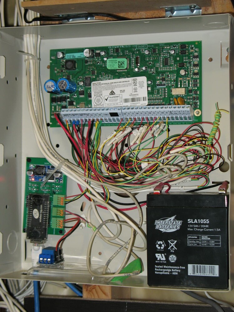
Yes, the battery (rechargable) is usually housed inside the DSC alarm panel cabinet. From the photo post by you before, I could not see any rechargable battery. Photo of the inside of my security panel is shown below, you can find the rechargable battery (black rectangular cube) on the lower right corner.
Congratulation on what you achieved, I can feel how excited you are. There is nothing looks horrible as long as it works. Actually your breakout board comes with pin header (black with a row of square holes) and screw terminals. You can also insert the wire of resistor into the corresponding holes, that might be a little easier.
As far as I recall, there were a couple of PCB designs for this project available, two of which are available on Dilbert66 esphome-dsckeybus repo. The first one was designed by Pipe Developer, also the one I used few years ago. The second was designed for WT32-ETH01 ESP module with Ethernet interface. The third one employs opto-isolator and the ESP32 module that you are using right now. You can take a while to read his post on Mar 2023.
Bear in mind both Pipe Developer designs use surface mount instead of metal film (the one you are using now) resistors. You can use either metal film or surface mount resistors on the Ethernet design. Pity was the WT32-ETH01 module does not come with USB interface, so you need an USB device to program the module the first time. You can update the firmware through Ethernet after though.
To get a printed circuit board without design you own, it is simple. Download the PCB design zip file (contains 6 to 7 Gerber and drill files) and upload the file to PCB manufacturing website, it will show your design and give you a quote for 5 pieces, almost instantly. I used PCBway for my first project (PCB designed by Pipe Developer). Recently I switched to JLCPCB. I believe there are a few more manufacturers who offer very competitive price.
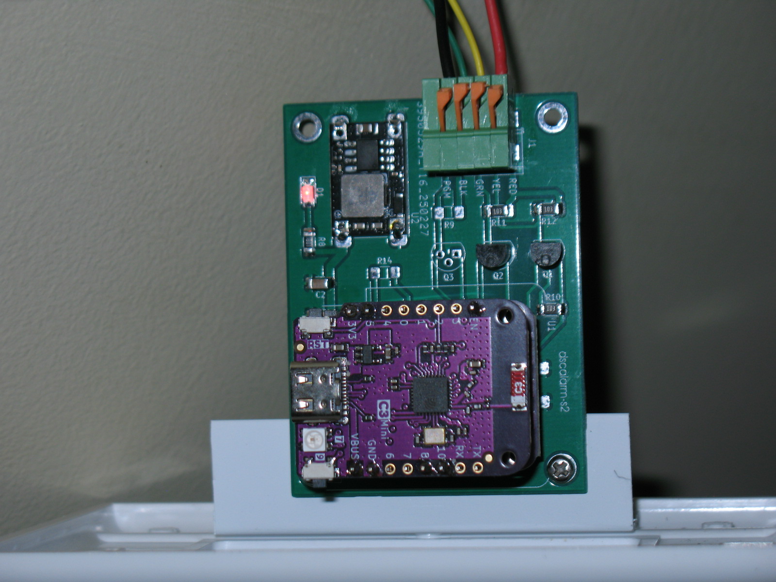
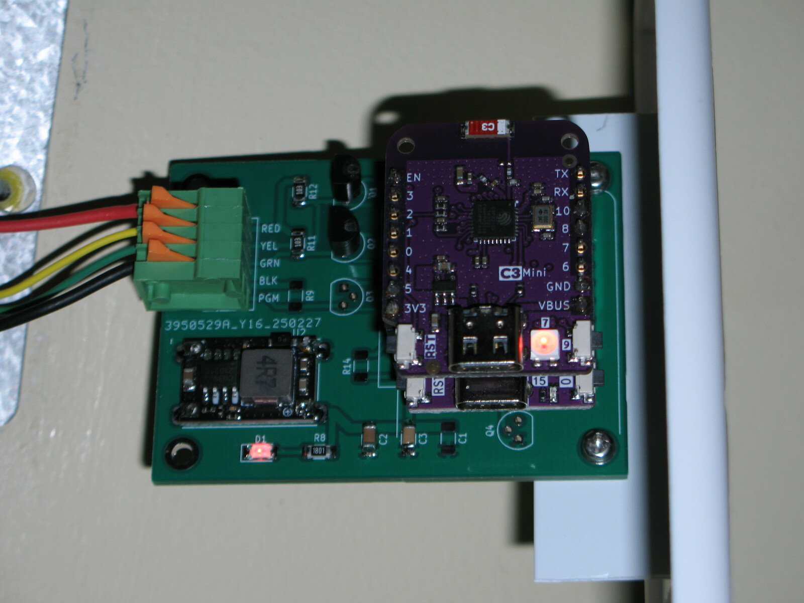
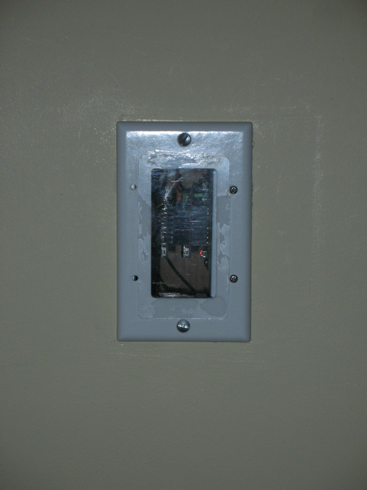
I designed a new PCB for DSC alarm panel interface lately that supports both resistor divider and MOSFET level shifter version. It was built so that I can fit the interface module inside the hole in the dry wall after I removed one of the DSC keypad. I have not uploaded the design as I thought nobody would have interest in it.

@wkchick thank you for sharing that ! I have a couple of questions for you :
-
when we get the PCB printed and shipped, would it already have all the components(resistors/transistors) soldered to it and we could just connect the 4 wires ? or would we still need solder various components? are there services that automatically do that for us? Ideally, I would love to get a board that has all the components already layed out and soldered and I could just plug in those 3-4 wires.
-
Could you please share your design in github or some other place? also your board looks tinier than mine, I am guessing it is another variant of esp32?
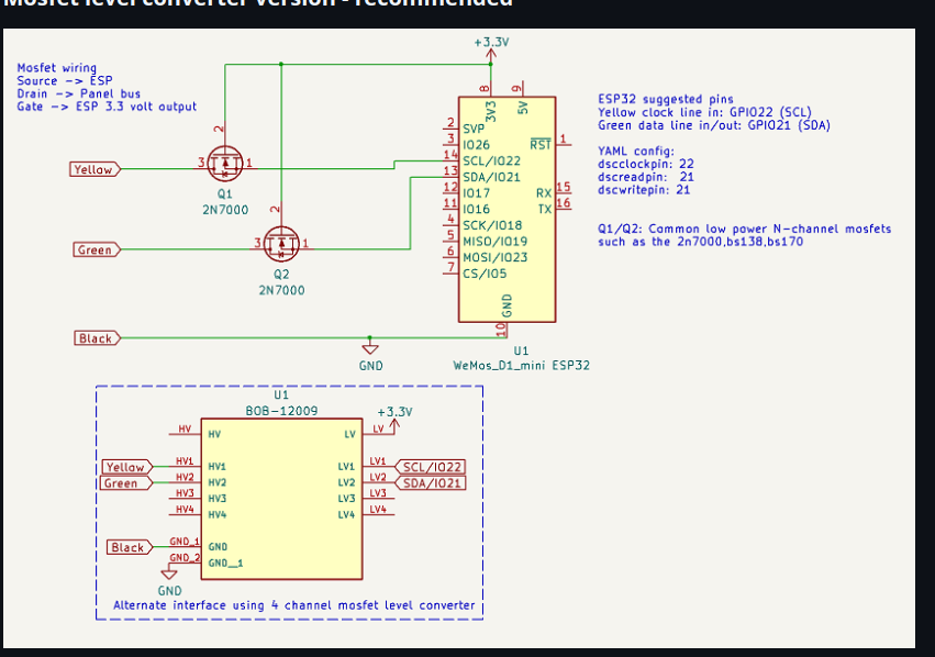
I like those c3 supermini’s. So compact for this use. If you use the dev branch version, you can control pin polarity and are able to simplify the wiring quite a bit using only a 4 channel level shifter and the esp. The data line runs in bidirectional mode so can tx and rx on the same pin. Only 2 components needed. You would in this case use the alternative dotted circuit instead of the two mosfets. It is the most reliable connection as well as being the simplest.
I have been using this with ESP8266 for some years without problems.
But now I cant get the alarm panel to work in Home Assistant after a fresh install.
All door- and motion sensors visible and working.
But I can not arm and disarm from HA.
The alarm panel is nowhere to find…
I dont think external_components have been downloaded?
There are no visible files after compiling and updating the DscAlarm.yaml file.
Do I need some code in configuration.yaml?
The log-file seems ok except from the dsc_alarm_panel…
INFO Reading configuration /config/esphome/DscAlarm.yaml…
INFO Updating https://github.com/Dilbert66/esphome-components.git@main
…
[11:02:09][W][component:237]: Component dsc_alarm_panel took a long time for an operation (77 ms).
[11:02:09][W][component:238]: Components should block for at most 30 ms.
- Yes, some PCB fabrication service also provides assembly but I have never tried it before. I have no idea how to pass on technical information required (e.g. R9 = 10K) to the assembly service. It was pretty standard and has been used decades for transferring Gerber files for the PCB. I just spent a few bucks every time to have bare PCB fabricated and then shipped to me.
- I can upload the PCB zip file to GitHub but I have not used it for years. It might take a little longer. I must agree with Alain (Dilbert66) that right now the simplest, most elegant solution is to pick a small ESP module and a 4-channel level shifter module (e.g. BOB-12009). Then there are only four wires from the ESP to the level shifter (+3.3V, GND, GPIO21, GPIO22) and then four wires to your DSC alarm panel (+12V, GND, DATA and CLK), nothing more than that! The ESP module will regulate the USB power to provide 3.3V output. You can forget about transistors, resistors etc. If you pick certain smaller ESP module, it is probably to stack them together with size smaller than your thumb. I wasn’t aware of this as those level shifters usually stated for bidirectional interface of 3.3V to 5V, but the MOS devices used can actually operate up to 60V (on the HV side)! BTW, the HV input of the BOB-12009 should connect to RED wire of DSC alarm panel.
- Yes, I used a smaller size ESP module (d1-mini), that was designated in the Pipe Developer design years ago and I kept that. There are several variants of d1-mini, the original ESP8266, d1-mini ESP32, ESP32-S2, ESP32-C3 etc. In my photo, there are two modules (ESP32-S2 and ESP-C3) stacked, both sharing the same interface. I used two modules to implement ESPhome API, MQTT, as well as Telegram notification (software also developed by Dilbert66).
- Lately I switched to even smaller C3 SuperMini (size even small and allowed to solder on another circuit board) as mentioned by Alain. This DSC project as well as other ESPhome project don’t need too many I/O pins. Thanks to ESPhome now many features can be implemented with very few I/Os. For example, my HVAC monitor with 3 temperature probes (one-wire component), 1 CT-clamp current sensor (1 analog input) and OLED display (i2c, 2 I/Os), with which c3 Supermini can provide more than enough I/O pins.
Edit: Latest PCB files uploaded here [PCB Layouts/dscalarm-s2](https://PCB Layouts/dscalarm-s2)
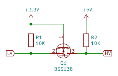
Actually, the red wire is not used at all and no connection needed to the HV input. The circuit is correct as drawn. The reason you don’t need the HV signal is that pullups are not needed in this case as the panel bus itself has an internal 10k pullup and on the ESP side the pin’s are configured with an internal software activated pullup which eliminates the need to use external pullup resistors simplifying the design.
This is a typical mosfet level shifter as used in the bob-12009. I’ve simply eliminated the need for the 10k pullups. As you noted, the bs138 used can easily handle up to 50v.
I run a c3 with the API, MQTT , my web_server , the DSC alarm component and telegram all on one chip. Uses most of the resources but works well! Even though it’s single core, it’s a powerfull little chip.
You’ll need to provide more details here. What did you change? Did you change any pin numbers in the config to match your old config? Did you configure your zones, etc. You won’t see visible files as it’s done in a temp folder by the esphome compilation. You just need to configure the yaml correctly. If you can’t arm and disarm from HA , HA is not seeing your esp. You need to add it to ha like any esphome devices. I’m not going to go into the HA setup as it’s all documented on the ESPHOME website when adding a device.
What an awsome project. I have been using it for about 4 years with no problems. Last month I needed to update my code due to the new version of ESPhome. I am now getting the following messages. I am using ESP8266? Any suggestions would be appreciated.
[12:31:47][E][CMD:843]: 2025-03-28 12:31  F2 16 02 00 00 00 00 62 63 02 45 43 F5
[12:31:47][C][template.binary_sensor:028]: Template Binary Sensor 'Alarm Tamper switch (z6)'
[12:31:47][C][template.binary_sensor:028]:   Device Class: 'window'
[12:31:47][C][template.binary_sensor:028]: Template Binary Sensor 'not used (z7)'
[12:31:47][C][template.binary_sensor:028]:   Device Class: 'window'
[12:31:47][C][template.binary_sensor:028]: Template Binary Sensor 'check comm device (z103)'
[12:31:47][C][template.binary_sensor:028]:   Device Class: 'problem'
[12:31:47][C][template.binary_sensor:028]: Template Binary Sensor 'Ready (rdy_1)'
[12:31:47][C][template.binary_sensor:028]: Template Binary Sensor 'Ready (rdy_2)'
[12:31:47][C][template.binary_sensor:028]: Template Binary Sensor 'Trouble (trbl_1)'
[12:31:47][C][template.binary_sensor:028]:   Device Class: 'problem'
[12:31:47][E][CMD:843]: 2025-03-28 12:31  F7 02 00 03 10 08 00 1C 08 02 00 00 2A
[12:31:47][E][INFO:1158]: Display to partition: 01
[12:31:47][D][text_sensor:064]: 'Line1 (ln1_1)': Sending state '*** DISARMED ***'
[12:31:47][D][text_sensor:064]: 'Line2 (ln2_1)': Sending state 'Rdy to Arm 12:27'
[12:31:47][E][INFO:1185]: Prompt: *** DISARMED ***
[12:31:47][E][INFO:1186]: Prompt: Rdy to Arm 12:27
[12:31:47][E][INFO:1187]: Beeps: 0

[12:31:47][D][binary_sensor:036]: 'Ready (rdy_1)': Sending state ON
[12:31:47][W][component:237]: Component vista_alarm_panel took a long time for an operation (145 ms).
[12:31:47][W][component:238]: Components should block for at most 30 ms.
[12:31:47][C][template.binary_sensor:028]: Template Binary Sensor 'Trouble (trbl_2)'
[12:31:47][C][template.binary_sensor:028]:   Device Class: 'problem'
[12:31:47][C][template.binary_sensor:028]: Template Binary Sensor 'Bypass (byp_1)'
[12:31:47][C][template.binary_sensor:028]: Template Binary Sensor 'Bypass (byp_2)'
[12:31:47][W][component:170]: Component debug cleared Warning flag
[12:31:47][C][template.binary_sensor:028]: Template Binary Sensor 'Away (arma_1)'
[12:31:47][C][template.binary_sensor:028]: Template Binary Sensor 'Away (arma_2)'
[12:31:47][C][template.binary_sensor:028]: Template Binary Sensor 'Armed (arm_1)'
[12:31:47][C][template.binary_sensor:028]: Template Binary Sensor 'Armed (arm_2)'
[12:31:47][C][template.binary_sensor:028]: Template Binary Sensor 'Stay (arms_1)'
[12:31:47][C][template.binary_sensor:028]: Template Binary Sensor 'Stay (arms_2)'
[12:31:47][C][template.binary_sensor:028]: Template Binary Sensor 'Instant (armi_1)'
[12:31:47][C][template.binary_sensor:028]: Template Binary Sensor 'Instant (armi_2)'
[12:31:47][C][template.binary_sensor:028]: Template Binary Sensor 'Night (armn_1)'
[12:31:47][C][template.binary_sensor:028]: Template Binary Sensor 'Instant (armi_2)'
[12:31:47][C][template.binary_sensor:028]: Template Binary Sensor 'AC (ac)'
[12:31:47][C][template.binary_sensor:028]:   Device Class: 'plug'
[12:31:47][C][template.binary_sensor:028]: Template Binary Sensor 'Chime (chm_1)'
[12:31:47][C][template.binary_sensor:028]: Template Binary Sensor 'Chime (chm_2)'
[12:31:47][C][template.binary_sensor:028]: Template Binary Sensor 'Alarm (alm_1)'
[12:31:47][C][template.binary_sensor:028]: Template Binary Sensor 'Alarm (alm_2)'
[12:31:47][C][template.binary_sensor:028]: Template Binary Sensor 'Battery (bat)'
[12:31:47][C][template.binary_sensor:028]:   Device Class: 'problem'
[12:31:47][C][template.text_sensor:020]: Template Sensor 'System Status (ss_1)'
[12:31:47][C][template.text_sensor:020]:   Icon: 'mdi:shield'
[12:31:47][C][template.text_sensor:020]: Template Sensor 'System Status (ss_2)'
[12:31:47][C][template.text_sensor:020]:   Icon: 'mdi:shield'
[12:31:47][C][template.text_sensor:020]: Template Sensor 'Line1 (ln1_1)'
[12:31:47][C][template.text_sensor:020]: Template Sensor 'Line2 (ln2_1)'
[12:31:47][C][template.text_sensor:020]: Template Sensor 'Zone Status (zs)'
[12:31:47][C][template.text_sensor:020]: Template Sensor 'Beeps (bp_1)'
[12:31:47][C][template.text_sensor:020]: Template Sensor 'Beeps (bp_2)'
[12:31:47][C][template.switch:068]: Template Switch 'vistaalarm-new Connection'
[12:31:47][C][template.switch:070]:   Icon: 'mdi:shield-link-variant'
[12:31:47][C][template.switch:090]:   Restore Mode: always OFF
[12:31:47][C][template.switch:057]:   Optimistic: NO
[12:31:47][C][restart:068]: Restart Switch 'restart_switch'
[12:31:47][C][restart:070]:   Icon: 'mdi:restart'
[12:31:47][C][restart:090]:   Restore Mode: always OFF
[12:31:47][C][safe_mode.switch:068]: Safe Mode Switch 'Safe Mode'
[12:31:47][C][safe_mode.switch:070]:   Icon: 'mdi:restart-alert'
[12:31:47][C][safe_mode.switch:090]:   Restore Mode: always OFF
[12:31:47][C][web_server:285]: Web Server:
[12:31:47][C][web_server:286]:   Address: vistaalarm-new.local:80
[12:31:47][C][sntp:042]: SNTP Time:
[12:31:47][C][sntp:045]:   Server 0: '0.pool.ntp.org'
[12:31:47][C][sntp:045]:   Server 1: '1.pool.ntp.org'
[12:31:47][C][sntp:045]:   Server 2: '2.pool.ntp.org'
[12:31:48][C][mdns:116]: mDNS:
[12:31:48][C][mdns:117]:   Hostname: vistaalarm-new
[12:31:48][C][esphome.ota:073]: Over-The-Air updates:
[12:31:48][C][esphome.ota:074]:   Address: vistaalarm-new.local:8266
[12:31:48][C][esphome.ota:075]:   Version: 2
[12:31:48][C][safe_mode:018]: Safe Mode:
[12:31:48][C][safe_mode:019]:   Boot considered successful after 60 seconds
[12:31:48][C][safe_mode:021]:   Invoke after 10 boot attempts
[12:31:48][C][safe_mode:022]:   Remain in safe mode for 300 seconds
[12:31:48][C][api:140]: API Server:
[12:31:48][C][api:141]:   Address: vistaalarm-new.local:6053
[12:31:48][C][api:143]:   Using noise encryption: YES
[12:31:48][C][debug:021]: Debug component:
[12:31:48][C][debug:026]:   Free space on heap 'Heap Free'
[12:31:48][C][debug:026]:     State Class: ''
[12:31:48][C][debug:026]:     Unit of Measurement: 'B'
[12:31:48][C][debug:026]:     Accuracy Decimals: 0
[12:31:48][C][debug:026]:     Icon: 'mdi:counter'
[12:31:48][C][debug:027]:   Largest free heap block 'Heap Max Block'
[12:31:48][C][debug:027]:     State Class: ''
[12:31:48][C][debug:027]:     Unit of Measurement: 'B'
[12:31:48][C][debug:027]:     Accuracy Decimals: 0
[12:31:48][C][debug:027]:     Icon: 'mdi:counter'
[12:31:48][D][debug:035]: ESPHome version 2025.3.2
[12:31:48][D][debug:039]: Free Heap Size: 7648 bytes
[12:31:48][D][debug:041]: Flash Chip: Size=4096kB Speed=40MHz Mode=DOUT
[12:31:48][D][debug:050]: Chip ID: 0x00837577
[12:31:48][D][debug:051]: SDK Version: 2.2.2-dev(38a443e)
[12:31:48][D][debug:052]: Core Version: 3.1.2
[12:31:48][D][debug:053]: Boot Version=31 Mode=1
[12:31:48][D][debug:054]: CPU Frequency: 80
[12:31:48][D][debug:055]: Flash Chip ID=0x0016405E
[12:31:48][D][debug:056]: Reset Reason: Software/System restart
[12:31:48][D][debug:057]: Reset Info: Software/System restart
[12:31:50][E][CMD:843]: 2025-03-28 12:31  F6 01 00 00 00 00 00 00 00 00 00 00 00
[12:31:50][E][CMD:843]: 2025-03-28 12:31  A1 00 00 00 00 00 00 00 00 00 00 00 90
[12:31:51][E][EXT:843]: 2025-03-28 12:31  F6 01 A1 07 00 6F 6B 02 43 43 F6 00 00
[12:31:51][E][CMD:843]: 2025-03-28 12:31  F2 0E 02 00 00 00 00 57 FE EC 01 01 01
[12:31:51][E][CMD:843]: 2025-03-28 12:31  F7 02 00 03 10 00 00 1C 08 02 00 00 2A
[12:31:51][E][INFO:1158]: Display to partition: 01
[12:31:51][E][INFO:1185]: Prompt: *** DISARMED ***
[12:31:51][E][INFO:1186]: Prompt: Rdy to Arm 12:27
[12:31:51][E][INFO:1187]: Beeps: 0

[12:31:51][W][component:237]: Component vista_alarm_panel took a long time for an operation (132 ms).
[12:31:51][W][component:238]: Components should block for at most 30 ms.
[12:31:51][E][CMD:843]: 2025-03-28 12:31  F6 01 00 00 00 00 00 00 00 00 00 00 00
[12:31:51][E][EXT:843]: 2025-03-28 12:31  F6 01 E1 0C 00 68 62 02 45 43 F5 31 FB
[12:31:51][E][CMD:843]: 2025-03-28 12:31  E1 00 00 00 00 00 00 00 00 00 00 00 90
[12:31:52][E][CMD:843]: 2025-03-28 12:31  F2 0E 02 00 00 00 00 50 FE FE EC 01 01
[12:32:01][E][CMD:843]: 2025-03-28 12:32  F7 02 00 03 10 08 00 1C 08 02 00 00 2A
[12:32:01][E][INFO:1158]: Display to partition: 01
[12:32:01][E][INFO:1185]: Prompt: *** DISARMED ***
[12:32:01][E][INFO:1186]: Prompt: Rdy to Arm 12:27
[12:32:01][E][INFO:1187]: Beeps: 0

[12:32:01][W][component:237]: Component vista_alarm_panel took a long time for an operation (131 ms).
[12:32:01][W][component:238]: Components should block for at most 30 ms.
[12:32:01][E][CMD:843]: 2025-03-28 12:32  F6 01 00 00 00 00 00 00 00 00 00 00 00
[12:32:01][E][EXT:843]: 2025-03-28 12:32  F6 01 21 0C 00 69 62 02 45 43 F5 31 FB
[12:32:01][E][CMD:843]: 2025-03-28 12:32  21 00 00 00 00 00 00 00 00 00 00 00 90
[12:32:01][E][CMD:843]: 2025-03-28 12:32  F2 0E 02 00 00 00 00 51 FE FE EC 01 01
[12:32:11][E][CMD:843]: 2025-03-28 12:32  F7 02 00 03 10 08 00 1C 08 02 00 00 2A
[12:32:11][E][INFO:1158]: Display to partition: 01
[12:32:11][D][text_sensor:064]: 'Line1 (ln1_1)': Sending state '*** DISARMED ***'
[12:32:11][D][text_sensor:064]: 'Line2 (ln2_1)': Sending state 'Rdy to Arm 12:27'
[12:32:11][D][text_sensor:064]: 'Beeps (bp_1)': Sending state '0'
[12:32:11][E][INFO:1185]: Prompt: *** DISARMED ***
[12:32:11][E][INFO:1186]: Prompt: Rdy to Arm 12:27
[12:32:11][E][INFO:1187]: Beeps: 0

[12:32:11][D][text_sensor:064]: 'System Status (ss_1)': Sending state 'disarmed'
[12:32:11][D][text_sensor:064]: 'Zone Status (zs)': Sending state 'OP:3'
[12:32:11][W][component:237]: Component vista_alarm_panel took a long time for an operation (172 ms).
[12:32:11][W][component:238]: Components should block for at most 30 ms.
[12:32:11][E][CMD:843]: 2025-03-28 12:32  F6 01 00 00 00 00 00 00 00 00 00 00 00
[12:32:11][E][CMD:843]: 2025-03-28 12:32  61 00 00 00 00 00 00 00 00 00 00 00 90
[12:32:11][E][EXT:843]: 2025-03-28 12:32  F6 01 61 0C 00 6A 62 02 45 43 F5 31 FB
[12:32:11][E][CMD:843]: 2025-03-28 12:32  F2 0E 02 00 00 00 00 52 FE FE EC 01 01
[12:32:20][E][CMD:843]: 2025-03-28 12:32  F6 01 00 00 00 00 00 00 00 00 00 00 00
[12:32:20][E][EXT:843]: 2025-03-28 12:32  F6 01 A1 0C 00 6B 6B 0B 45 43 F5 33 FB
[12:32:20][E][CMD:843]: 2025-03-28 12:32  A1 00 00 00 00 00 00 00 00 00 00 00 90
[12:32:20][E][CMD:843]: 2025-03-28 12:32  F2 0A 02 00 00 00 00 53 FE FE 30 83 00
[12:32:20][E][CMD:843]: 2025-03-28 12:32  F6 01 00 00 00 00 00 00 00 00 00 00 00
[12:32:20][E][EXT:843]: 2025-03-28 12:32  F6 01 E1 07 00 6C 6B 02 43 43 B9 00 00
[12:32:20][E][CMD:843]: 2025-03-28 12:32  E1 00 00 00 00 00 00 00 00 00 00 00 90
[12:32:20][E][CMD:843]: 2025-03-28 12:32  F2 0E 02 00 00 00 00 54 FE EC 01 01 01
[12:32:21][E][CMD:843]: 2025-03-28 12:32  F7 02 00 03 10 00 00 1C 08 02 00 00 2A
[12:32:21][E][INFO:1158]: Display to partition: 01
[12:32:21][E][INFO:1185]: Prompt: *** DISARMED ***
[12:32:21][E][INFO:1186]: Prompt: Rdy to Arm 12:27
[12:32:21][E][INFO:1187]: Beeps: 0

[12:32:21][D][binary_sensor:036]: 'Family room motion (z3)': Sending state OFF
[12:32:21][D][text_sensor:064]: 'Zone Status (zs)': Sending state ''
[12:32:21][W][component:237]: Component vista_alarm_panel took a long time for an operation (147 ms).
[12:32:21][W][component:238]: Components should block for at most 30 ms.
[12:32:21][E][CMD:843]: 2025-03-28 12:32  F6 01 00 00 00 00 00 00 00 00 00 00 00
[12:32:21][E][EXT:843]: 2025-03-28 12:32  F6 01 21 0C 00 6D 62 02 45 43 F5 31 FB
[12:32:21][E][CMD:843]: 2025-03-28 12:32  21 00 00 00 00 00 00 00 00 00 00 00 90
[12:32:21][E][CMD:843]: 2025-03-28 12:32  F2 0E 02 00 00 00 00 55 FE FE EC 01 01
What’s the problem exactly? The f6 messages are AUI data which comes from a touch panel. I assume you used the master branch version code and that one does not support aui emulation so what you are seeing is your actual touch panel requesting data from the alarm panel.
Just got all set up Spectacular work BTW…, everything works well with my DSC 1616 , ESP32 wroom , Home assistant. the only issue I have is that the Keypad Display in the card on my Dashboard stays blank. I do get a reply in the log for line 1 and 2 , ( and can see the states change in the entities for each message,) but nothing in the display itself. Have tried different browsers cache cleared restarts etc etc All keys do work from the card ( arming , entering codes, even programming.) Basically EVERYTHING works, just no Keypad display on the card or updating the card visually.
UPDATE: Got it sorted… Had to get my entities correct in the card setup ALL good ! Works great
The first PCB was designed without any 10K pull up resistors, neither on the source or drain pin of MOSFET. However when I use the same GPIO pin for dscreadpin and dscwritepin in the yaml file, the DSC1832 panel beeps unstop with Trouble light on. I have no oscilloscope but I guess it was the DATA pin. I first tried to add a 10K pull up resistors on the source pin but it did not help. Problem was solved immediately when I add a 10K pull up resistors on the drain pin to RED (+12V) pin. I then modified the PCB with both source and drain pin of MOSFET exactly the same as BOB-12009.
I noticed the DSC panel bus has internal 10K pull up because the LED on my circuit flickers even without connecting the RED (+12V) wire. I believe the above issue was because I drive my ESP module with power from DSC panel instead of a separate power supply.
Isn’t it API and MQTT cannot co-exist in the same yaml file? I am using a ESP32-S2 for API and ESP32-C3 for MQTT. The ESP32-S2 is even more powerful than the the ESP32-C3. I would love to combine this two functions into one single ESP module.
I am using the ESPhome Telegram function (not the standalone Arduino C++ Telegram) developed by you on a separate ESP module but found it a little sluggish (needs a couple of second to respond). It is not connected to the DSC panel. I used it to execute some functions through Telegram, e.g. take snapshot of CCTV camera and send it to my cellphone via Telegram. For some unknown reason, the Home Assistant server just does not respond to anything sent from Telegram.