Sorry, had a missed file when i pushed it to dev. Should compile now.
Many thank Alain! Zone statuses looks OK again now!
Out of curiosity: what was breaking it? Was it one of the esphome updates?
I added logic to capture tampers but for some reason it was getting set on your system but not cleared so I need to do more testing on the tamper comms to determine what’s missing.
Let me know if I can assist in any way.
Hi All, thank you for all of your hard work and your contributions and sharing your work with everyone. I am new to this and stumbled on this thread and it has given me hope.
I have an old DSC alarm system(PC1616) and I was using Envisalink 4 module for it and was able to connect it to home assistant and while it worked for about a year, the module stopped working (no LEDs turn on anymore) and looks like the only option is to buy another $100 board or buy even more expensive board from konnected. I too am tried of these expensive boards and I want to learn to do this myself so that I can control and update things as needed and in the process, gain some experience and learn some electronics.
As I am a newbie to this project, so I want to ask, can I use this project https://github.com/Dilbert66/esphome-dsckeybus with my alarm system? would that be compatible? If not what all would I have to do?
My question are these: In this PC1616 alarm system, there seems to be a support of 6 zones? and I see those 5 other wire pairs (black and red) closed with white cover that dont seem to be connected anywhere and floating around , does that mean those are other sensors that are connected to windows/doors but because the board didnt have more than 6 zones support, they could not be used?
So in this project does this Alarm system stay and we use the ESP module with it? or does this alarm system completely get replaced with the ESP system? (For example for the envisalink board, all I had to do was connect red, black, yellow, green cables to board and that was it) .
Please assume I am a newbie and explain it to me step by step what all I would need to do and please including parts/links and instructions. All I want to be able to do is to be able to use my existing sensors in doors/windows and have them report to home assistant when triggered.
My experience in electronics is pretty basic ( I can program almost anything and have worked with various arduinos, raspberry pi, and other boards, I can connect some wires, and maybe able to do some soldering, but I do not have experience designing PCBs)
Here are the pictures of the alarm system (PC1616) and the keypad(not sure if this is important or not but it says : PC1555RKZ)

I would really appreciate your help.
Thank you!
Neil
The project works just like the envisalink. You wire up 4 wires to the panel and power the esp. It emulates a keypad and sends all sensor data to home assistant. You would leave your alarm panel as is and yes, your panel is compatible with the project. Unfortunately, I don’t have the time to give you step by step info. I provide the code, some details and limited support. You’ll have to figure it out as it is designed to be a free DIY project. The documentation is there and you can read through the thread.
Correct me if I am wrong, in your photos all 6 zones are connected and used. They are not floating around and covered in white. Those are EOL resisters (one per zone) covered in white heat shrink tubes. Will provide more information after I returned home.
@Dilbert66 thank you and that is fair. My biggest unknown right now is the wiring and I hope I can figure it out and get it working. I will get the esp32 board delivered today and I cant wait to try to put it all together and I will be happy to share what comes of it and maybe help do any documentation or any changes if I can.
@wkchick thank you for looking at it, the 6 zones are connected, but if you look at the second picture on the top right side, you see there are those 5 pairs of black and red cables that are covered with a white cover that says dolphin? I was asking about those? My assumption was that those were extra contact sensor wires that are probably hooked up somewhere in the house but since the PC1616 board only had 6 zones available those extra ones could not be plugged in.
would that be a correct assumption? would I be able to try to connect those to the esp32 module as well?
@Neil25 That 5 pairs of black and red cables, according to the PC1616 Installation manual, are for telephone. They are very likely connected to your phone jack, if you are still using it.
@wkchick ah okay, thank you for that. I was hoping I would somehow be able to get a granular read of different windows. Currently it looks like various windows are combined into zone 4(master windows), 5(bedroom windows) and 6(all other windows) etc rather than individual ones. While that would be nice I guess that is not so important right now.
so far I was able to get started with this esp 32 module (https://www.amazon.com/dp/B0DN5ZJZSL?ref=ppx_yo2ov_dt_b_fed_asin_title ) with arduino IDE and was able to compile/upload some code to get it connected to my wifi! next I will start learning about wiring diagrams(a bit intimidating, hopefully I will be able to piece everything together from this thread) etc and I will report back.
One question I have is, should I be looking at the master branch or the dev branch for this repo?: GitHub - Dilbert66/esphome-dsckeybus: Esphome custom configuration for interfacing to a DSC POWERSERIES alarm system
use the “dev” branch. Dev will be pushed to master soon. As to wiring, you just need to wire the red,black,yellow,green wires just like a keypad or the envisalink module. The schematic says it all.
Yeah, same for me. In my house, the alarm security panel installer wired all basement windows to one zone and all main floor windows to another zone. Even all PIR motion sensors from different floors are combined to one zone.
I recalled you mentioned Home Assistant and I presume you will use ESPhome instead of Arduino IDE. I suggest you should look at the dev branch of esphome-components
https://github.com/Dilbert66/esphome-components/tree/dev instead of repo esphome-dsckeybus. However, you still need to visit the latter repo for wiring diagram and description etc.
With the ESP32 breakout board you used, wiring should be pretty simple and easy. You need only four resistors for voltage divider to start with, you can power up your ESP32 module with USB power supply. Once you get the zone status on your ESPhome or Home Assistant that you can add the 1K resistor and transistor to control the DATA line of PC1616.
I am not familiar with the ESP32 module you used, so I don’t know which GPIOs you should use. You probably already knew you have to change the GPIO number in the yaml file accordingly.
Once you get everything works and you want a neat, tidy solution, you can find several PCB design in the esphome-dsckeybus repo.
Hi @wkchick ,
My breakout board and pinout diagram looks like this:


I was looking at the isolated version wiring and since I am new to all of this I think the hardware knowledge gap is too huge for me to be able to do this right away.
All I was able to deduce was I need to connect the yellow wire from the DSC panel to my GPIO 22 and green wire to GPIO 21, but then in the git repo, it talked about a green line in and a green line out, so I am not sure what I would be doing.
I think maybe I need to take a step back and learn how to read a diagram and identify various components and what they are and why they are there. For example, I have no idea what a optocoupler is or does or how/where to connect those resisters. So for now, I think I first need to start with the basic by learning how to wire a LED and turn it on etc LOL
In the meantime, you mentioned that I could find a PCB design in the repo, could I use one of those designs and have it printed and shipped to me and buy an exact esp32 board that works for it and simply connect the 4 wires(kind of like what I was doing with envisalink) and maybe do some soldering and be done with it? (since I am too much of a noob)
If this is possible, could you please let me know which design I should use and how to get it printed? like what file format would I need to upload and to what website etc…
I appreciate you putting up with my noob questions. I come from a purely software background and electronics is an unknown world to me.
It would be a little complicated for you to look at the isolated version. You can start with the simplest voltage (using only two resistors) divider version, then you need only four resistors to start with.
Yeah, there is a DATA (green) line out, but you can get the CLK and DATA in first and finish the DATA (with one resistor and one transistor) line out later. The DATA line out is for controlling the PC1616 through your Home Assistant (cellphone etc.). Simply make sure you get the signal from the PC1616 to the Home Assistant first.
All PCB on the repo use the voltage divider version. Yes, you can order them and shipped it to you for just a few dollars. Bear in mind, those PCB employs SMT resistors and might be a little challenge for your soldering technique.
ah okay, yes, I think for now, I would be happy with just being able to read the open/closed status and dont even want other features like controlling the alarm or passing data to it just yet. Just want to be able to see whats closed/open. I am rapidly learning about the fundamentals of electronics through youtube and learning about resistors and leds and bread boards etc. I will come up to speed soon hopefully.
I thought about suggesting a breadboard but you are so smart to buy a breakout board with your ESP32 module. You can just connect the resistors to the screw terminal and skip the breadboard idea. You can focus on this circuit diagram on esphome-dsckeybus repo:

You only need to connect the R2, R3, R4 and R5 on the circuit diagram to accomplish reading of PC1616 status. After you get it right, you can then consider connect the R1 and Q1 in the wiring diagram.
Edit: Disregard my previous post. That’s for the Vista20 panels. For the DSC, you do need R2/R3 and R4/R5. The yellow is the clock and the green is bidirectional data. I code interfaces for a couple different alarm systems and been known to confuse the two at times :(. The wiring is similar.
Hi Alain. I’m getting this error tonight while checking the alarm status via the keypad card:
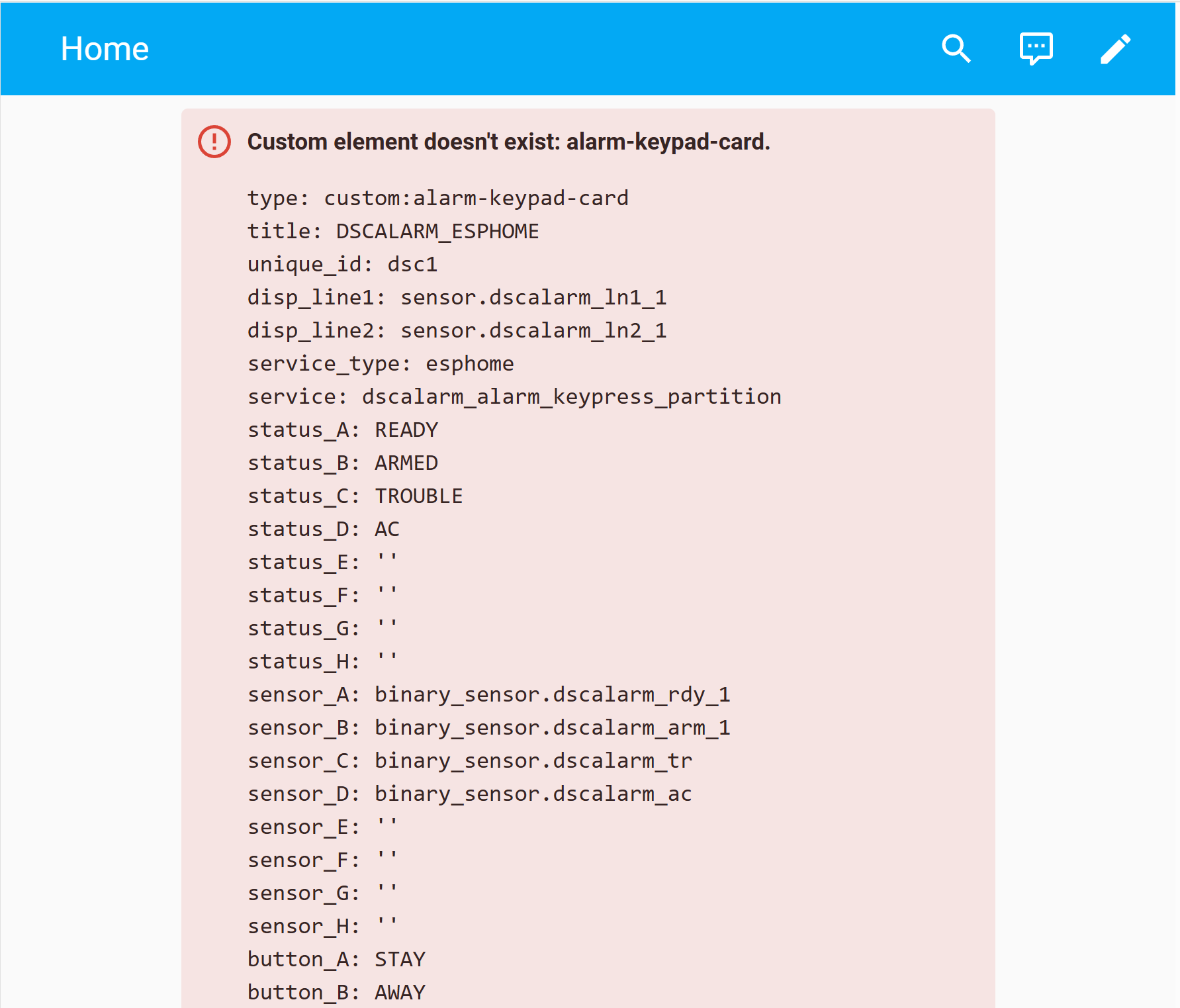
I checked the page loading in chrome via F12 and got these errrors:
Access to script at ‘https://unpkg.com/[email protected]/lit-html?module’ (redirected from ‘https://unpkg.com/lit-html@^1.0.0/lit-html?module’) from origin ‘http://192.168.0.135:8123’ has been blocked by CORS policy: No ‘Access-Control-Allow-Origin’ header is present on the requested resource.
Checking the links on the browser returns a Not found: [email protected]/lib/shady-render?module.
Any idea on how to run this locally instead of getting them online everytime.
I will look into the keypad card js to see if I can do that.
I’ll update it tomorow with a fix. There is a pending PR from feldsam that I will push which should take care of it.
Try using this include instead of the unpkg import;
const LitElement = Object.getPrototypeOf(customElements.get("ha-panel-lovelace"));
const html = LitElement.prototype.html;
const css = LitElement.prototype.css;
Ok I will give it a shot. Thanks.
Edit: Got it working with your suggestion. Thanks again !