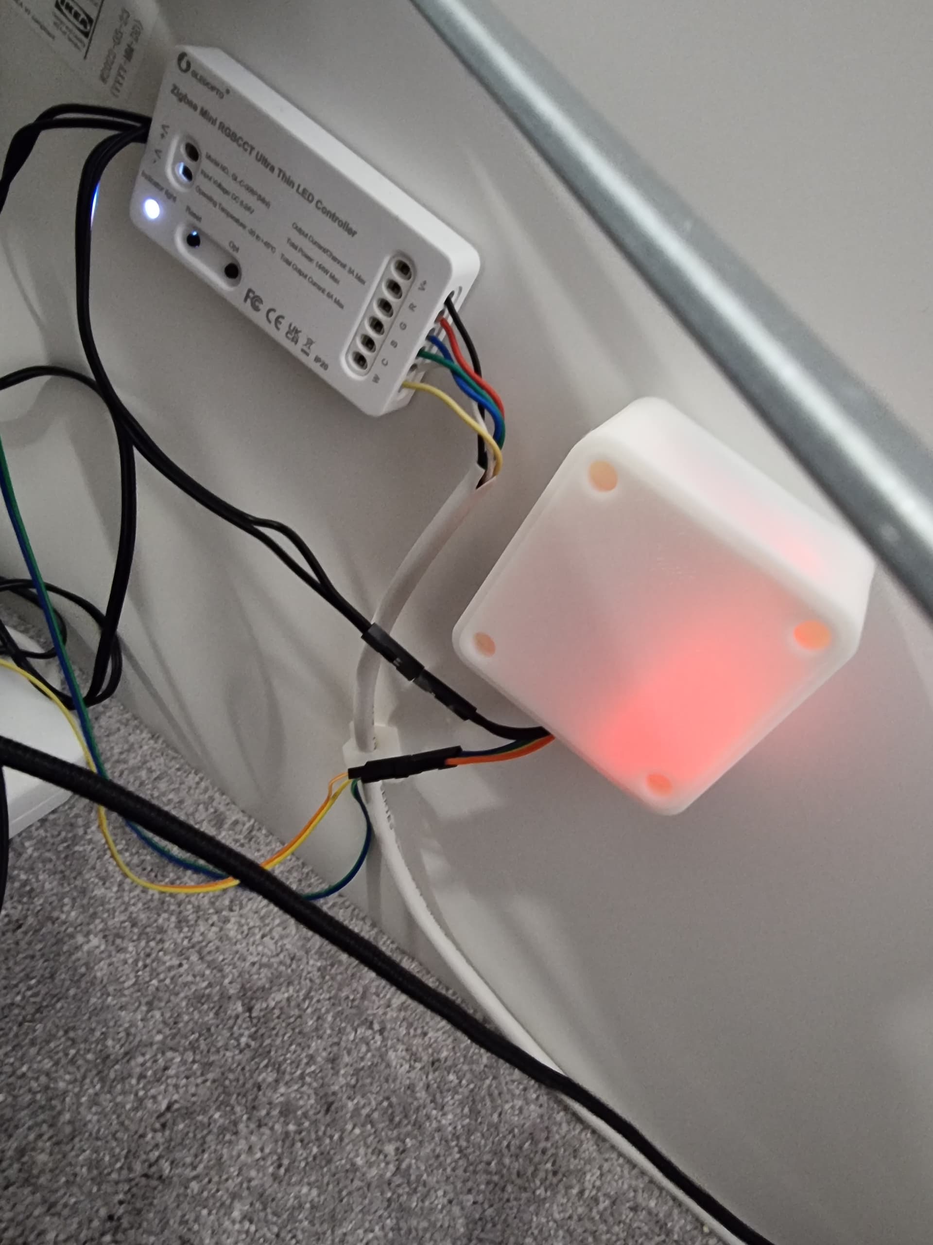
Just wanted to show off my version of this project! I did two sensors, one for each side of our king size bed and also included control of two RGB led strips that will run under each side of the bed frame to provide path lighting in the middle of the night when we need to get up. We have pets, and it’s always a crapshoot if you’re going to trip over someone or not without light.
Biggest struggle I had getting this to work was determining what to use for R1, since our matress does way too good of a job with weight distribution. When we are out of bed the FSR just showed open circuit. So I just picked a target trigger voltage and worked backwards from there to get a workable value for R1.
Just have to put it in a case and fit it to our bed!
So with the SF15-600 FSR available at aliexpress for 10$ a piece I also was not able to measure the resistance, although my cheap multimeter is supposed to measure up to 60MegaOhm. The multimeter just showed OL = open loop. I did not find a data sheet for the SF16-600 FSR.
I used the following tool to calculate the resistance from the voltage I got with a R1 resistor in place on the PCB: Voltage Divider Calculator. With R1=128kOhm, V1=3,306V and V2=3,267 I calculated the FSR with just the mattress on it still has a resistance of R2=10,7MegaOhm. With my body weight distributed by the mattress to the slat mounted FSR I get R2 from 9kOhm to 600kOhm depending on how I’m positioned on the mattress. One can try different R1 values in the calculator to find a sufficient difference between the V2 values depending on the weight related resistance of your FSR (R2). The suggested formula SQRT(R_in_bed*R_out_bed)=R1 indicated a R1 of 327kOhm to 2,5MegaOhm. The highest available resistor at hand had 128kOhms and still delivered great results. The sensor is very stable when the bed has only the static load of the mattress:
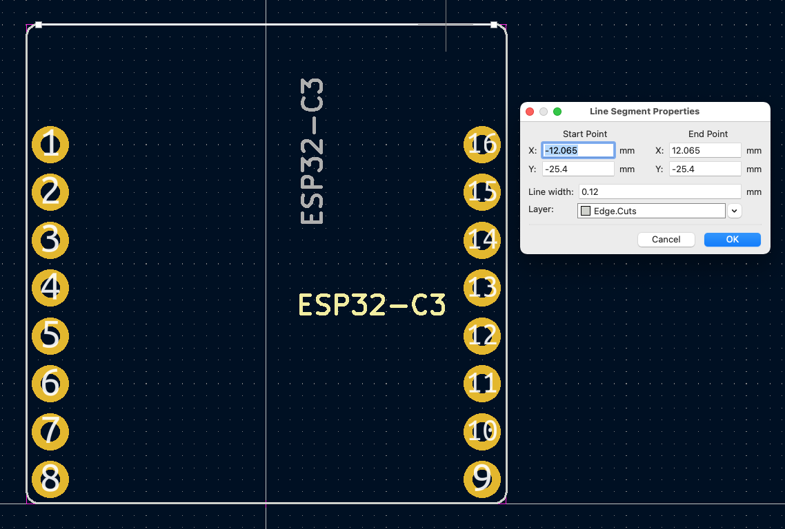
@florianmulatz Would you mind having a look at my kicad files and tell me what you think: GitHub - fhb/FSR-bed-sensor-Lolin-ESP32-C3: FSR Sensor using an Lolin ESP32-C3 pico (pin compatible to Login ESP32-C3 mini). I still have to figure out how to do a proper edge cut aligning with the outer silk mark of the ESP32-C3 pico. The PCB only has uses the area of the ESP32-C3 pico and includes the option to add a BME280 humidity/temperature sensor breakout. It’s an early prototype, I will put this together on a breadboard and then test it in a few weeks.
I thought it is fun that while on this side of the world we work with what we found, they may be look at demand and try to come up with something new. Did no meant to be offensive 9if it sounded like this).
I hope the sense of the ‘lol’ is now clearer to you and other readers
Best regards
I originally had Ikea Shortcut Buttons for my wife and I to push so the house knew what state it should be in, but my wife never pushed it, so this was a much needed project.
I followed your instructions and it works perfectly first go. With our Sleeping Duck mattress, my wife’s side had greater than 40M resistance so using a 100K resistor as recommended worked perfectly. I get a swing from 0.4v to 3.17V on both sides.
One thing I’m stoked about is that sleeping I get an average of 0.8v, but sitting up slightly and watching TV, I get closer to 2.2v, so I can make decisions based on whether we are in a sleep position or a seated position.
I had 12v powering my zigbee striplight controllers, so just split off that and added a 3.3v regulator to the ESP32. 3D printed a small enclosure for it all and it is tucked away nicely.
The board looks great but I think the position of the BME280 will not bring accurate readings because of the heat of the ESP itself. Therefore I would suggest a bigger PCB with the BME apart from the ESP.
Because of the silk, I had the same problem with my PCB (which I will not develop anymore - since I think your attempt looks quite better) so I decided just to remove the silk-marks from my footprint (you should be able to edit it with the footprint-editor)
Hi @brywithawhy!
I like the idea of powering the ESP through the ZIGBEE controller - honestly I never had that idea, although I also use a ZB controller for my BED downlights
Just wondering why you didn’t use a 5V buck converter? I think you get unstable operation with 3.3V on the ESP?
Thanks also for your suggestion regarding the thermal issue with the BME280. I will probably make it stick out of the case by moving the soldering points by a few millimetres, as the sensor is at the edge and putting the sensor out of the case should avoid any thermal issues. I will have to figure out a new enclosure design for this though
In my case the 128k resistor seemed to work great, but I get voltage spikes to 3.12V during the night, which is the same voltage level as with no body weight. It’s probably caused by me shifting my weight around (no, I don’t think I moved to the left bed side). I ordered resistors in the Megaohm range to test again and report back.
This looks ideal for a bed but what about my three-seat couch with recliners? How about one of these in each section to detect someone sitting, glued to the TV and motionless long enough that the motion sensors turn off the lights?
Thanks, it looked like the ticket, so I already went ahead and ordered two to set up his-n-hers detection for my queen bed.
I also just found this link for what seems to be the latest cat’s ass in detection!
Upon reading more about mmWave radar though, I am under the impression it is still a motion sensor, just many MANY times more sensitive…