Because as others have noted it is not a touch sensor, so that connection method was not initially considered.
Hi Guys,
I’ve updated the PCB a little bit (to be smaller dimensions - also the groundplate is now over the whole PCB)


Also - please I’ve created a GitHUB Repository on that - feel free to download (or contribute if you want)
Cheers Flo
1 Like
Thanks a lot! the spacing for the screw terminals solder pins is 5mm. I also added 3d models in a local copy of your GitHub repository to get a better idea how the finished project looks like. I didn’t add the female headers though.

Has anyone used a shorter FSR - this one is 11 cm long but much cheaper.
Thx for that Felix - anyhow I’ve updated the design again to make the pcb smaller (45x32mm) and designed it to get VCC from external PSU. Also I added more descriptions on the PCB. The QR Code is a link to the github-repository where the KiCAD Files are located.

Cheers Flo
1 Like
I suppose so 
But I think with 11cm you will not get a reliable result, unless you do not turn over in your sleep and always stay in the same place 
Really nice ! Next step, a nice little box that could be printed
I don’t own a 3D printer nor do I know how to design 3D enclosures - so someone please help me out ![]()
These kind of sensors are been used for car seats.
When you sit at the car and wearing no safety belt then car will know …
I am using on of these at my chair’s office as occupancy sensor.
I have completed my project and I have to say I am very pleased with it.
It works smoothly without problems.
I would like to share with a small script which is using TTS and the Alexa’s Speech Synthesis Markup Language (SSML). Hope you enjoy it.
alias: Bed time
sequence:
  - delay: "00:00:01"
  - service: alexa_media.update_last_called
    data: {}
  - delay: "00:00:02"
  - service: media_player.volume_set
    data:
      volume_level: 1
      entity_id: "{{ states.sensor.last_alexa.state }}"
  - service: notify.alexa_media
    data_template:
      target: "{{ states.sensor.last_alexa.state }}"
      data:
        type: tts
      message: >-
        <speak>  {% set sleeptime =
        states('sensor.sleep_time_yesterday_for_makis') | float | round(1) %}
        {% set minutes = ((sleeptime %1) * 60) | int %}           {% set hours =
        sleeptime | int %}

        {% if sleeptime > 7 and sleeptime < 8 %}  {% set time_to_goal = (60 -
        minutes)   %}  {% else %}  {% set time_to_goal = (8 - sleeptime) |
        round(1)  %}  {% endif %}

        {% if sleeptime > 8 %}

        <amazon:emotion name="excited" intensity="high">

        The pre-defined sleep time has been reached. You slept {{ hours }} hours
        and {{ minutes }} minutes.

        </amazon:emotion>

        {% else %}

        <amazon:emotion name="disappointed" intensity="high">

        The pre-defined sleep time has not been reached.<break time="1s"/>

        You slept {{ time_to_goal }}  {% if sleeptime > 7 %}  minutes  {% else
        %} hours {% endif %}  less than the desired sleep time.

        </amazon:emotion>

        Try again tomorrow!

        <amazon:emotion name="excited" intensity="high"> Because sleep is
        essential to survival, and a key to living well over a long lifespan
        </amazon:emotion>

        {% endif %}

        </speak>
mode: single
icon: mdi:bed
Thank you for this - I am just putting the finishing touches on my build. I am a Grafana noob, would it be possible to share how you are able to format the sensor data as above? Specifically, how do you get the red shading to indicate the “Occupied” times?
Thank you again for this awesome tutorial!


Just a quick tip for those who aren’t keen on soldering to the leads:
I had success with a couple of female DuPont connectors and a good squeeze of the ol’ pliers to crimp them snugly.
1 Like
I will design a 3d printable housing once I got the ordered D1 mini ESP32 for the v1 pcb, which I just got with the maiI. I overlooked that you didn’t design the pcb for the more common regular D1 mini Esp8266. I don’t know how I missed this considering the totally different number of pins and the ESP32 string printed on the PCB. Just a quick look at the pin layout tells me the ESP8266 is not pin compatible.
I’m interested in why you switched to powering the pcb with a screw terminal? The usb plug is universal and easy to use with any old phone charger or usb hub.
I think it would make sense to design the pcb for the more common D1 mini ESP8266 or the newer S2 mini (ESP32), they are the only ones available with type C USB and even the ESP8266 should be more than capable for the job. What do you think? I might try to adapt your design to the mentioned boards later this year.
The d1 mini with the new pcb orientation would give us a compact design:
Hi Felix, yeah you’re right.
I just designed the PCB for what I had “on stock” and the author of this post also used ESP32. I’m not an electronic-expert but I think from what I read that ESP8266 s ADC is not capable of reading voltages above 1V - please correct me if I’m wrong. Also ESP8266 has only one ADC (adc0) - and I wanted to have one and only one sensor for my king-size bed.
Regarding the PSU - I made the experience that most of those “low-budget” usb-chargers do not give a reliable voltage output and I recognized that my ESP with those chargers drop WIFI-Connection frequently. I did not had this problem with “better” powers-supplies. (I didn’t have any of those ESPs with USB-C until now - maybe this problem is gone with this one since I think I read somewhere that USB-C has a more reliable and stable power supply ?!)
Maybe it makes sense to design the PCB to support both options. For example with an PowerJack like most electronical devices have one.
Cheers
Thanks for the swift answer, you are right the ESP8266 only supports one ADC and therefore is not an option.
The ESP32-S2 supports two ADC and has the same smaller footprint of the ESP8266 variant D1 mini and should be the ideal ESP board for this project: S2 mini — WEMOS documentation
I think the stability of the 5v usb power supply just depends on the power plug not the cable/connector type, but I don’t have any deeper knowledge on this. My ESPs are running on usb just fine
I have two aqara sensors and 2 FSRs on a box spring of a queen bed. I was noticing phantom triggers of bed sensing occupancy.
When I set them up, I hhave automations to turn on boolean sensors if the binary sensor from the fsr is triggered for 10 seconds, and only if me or my gf is home, I thought this would prevent the issue I am currently experiencing.
I have them in Z2M and noticed the ‘debounce’ option and set it to 1. Is this going to help or make it worse? I don’t know what it means and Z2m docs only mention if the sensor is ‘horizontal’ which I believe it is. Cam here to see if anyone else needed to debounce with FSRs
Good Morning Felix,
I’m not sure if the S2 mini is the right one since the GPIO Numbering is different (Reference)from the well known ESP8266/ESP32 mini (often referenced as “mini” or “D1”).
What do you guys think about this design? - I’ve reduced the board from 2 pins (+5V) and let space for putting the USB-Cable.

If you want to go with USB-C take one of these:
Cheers
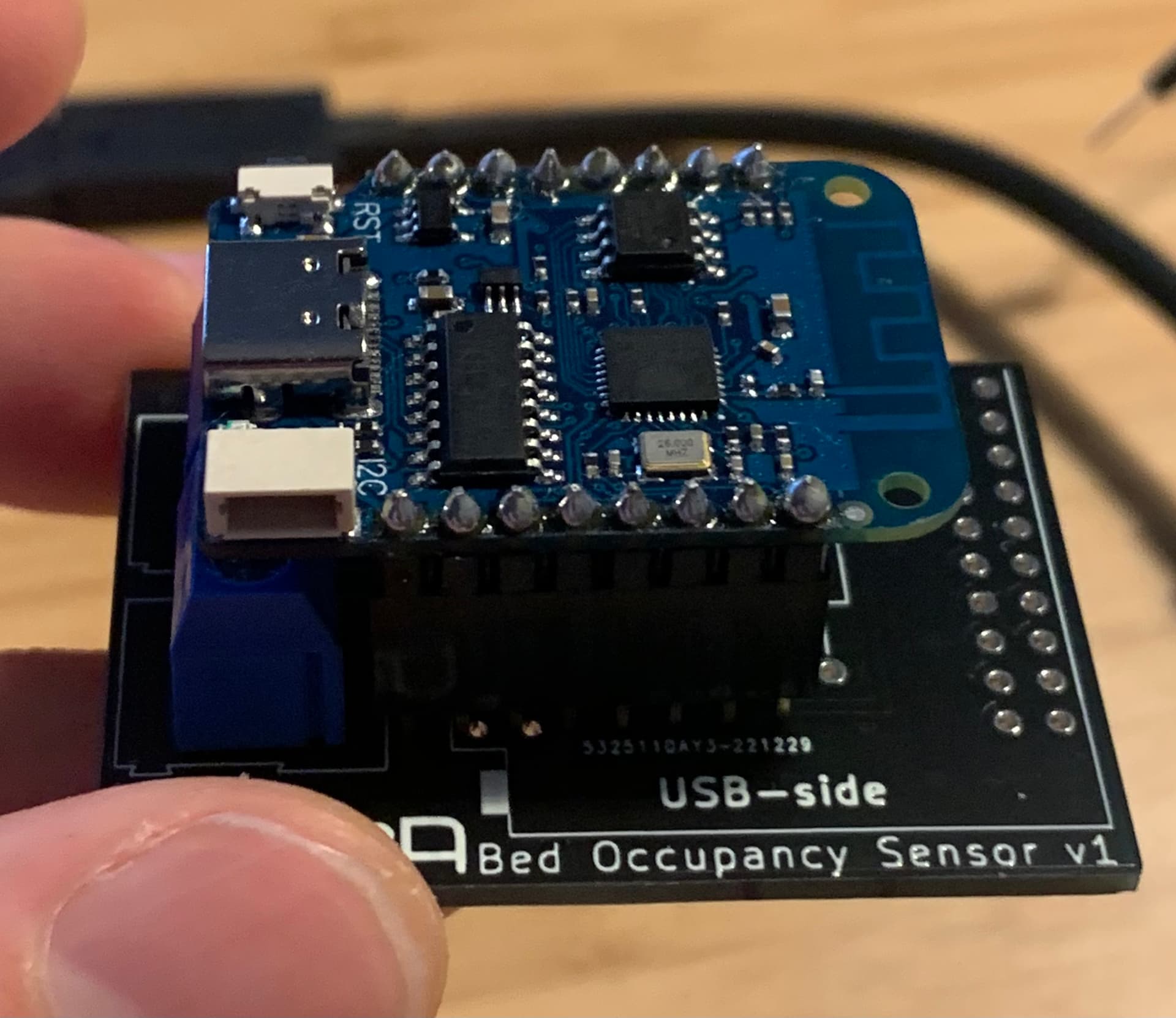
Hi - I received my v2 board today - and I recognized that I accidentally had the Footprint flipped on my PCB so I’t exactly the other way around see here


So in this design we do have the problem that the antenna is not free (like in the design-guidelines mentioned by @tom_l .
Anyhow it’s working at least for me. Since I have a nearby accesspoint my signal strenght is excellent →
[11:45:58][C][wifi:369]: Signal strength: -44 dB ▂▄▆█
I will anyhow update the design as soon I have time again
Cheers
**
PS: PLEASE DO NOT ORDER the v2 board as it has a design flaw.
**
Thanks for the type c board suggestions!
Yes, the pin layout, the pin count and the distance of the pin rows are different, so the pcb would need a redesign for the S2 from Wemos (which seems to be the successor of the Wemos D1 mini). I already ordered the D1 ESP32 so I’m happy to stick with the v1 or v2 pcb. I only suggested to adopt the Wemos S2 because it has type C usb and is smaller, newer and also cheaper than the D1 ESP32.
I like the design with just 4 screw terminals