GPIO Access
This guide provides instructions for utilizing various esp32 devices to monitor contact sensors. I’ll have to come back and refine this another day.
Originally I utilized gpio pins on my odroid N2+ to monitor my wired door contract sensors, which I documented here. HA OS doesn’t provide access to the GPIO pins, so I needed an alternative approach. My first approach was to integrate a raspberry pi 4 into the equation, as I also have routing requirements that aren’t an option with HA OS. The thread here gives the full details on the requirements I was trying to address. The GPIO specific implementation are the second post in that thread. While this worked, I didn’t like the extra power it required. The threads I include previously had some good alternative recommendation. As a result this post documents three other alternatives for accessing the contact sensor via ESP boards. Each board provides a different type of interface to HA.
Via ESP with Wired Ethernet
My first shot was utilizing an esp board that included a hardwired Ethernet interface. I selected the WT32-ETH01 ESP32 Development Board.
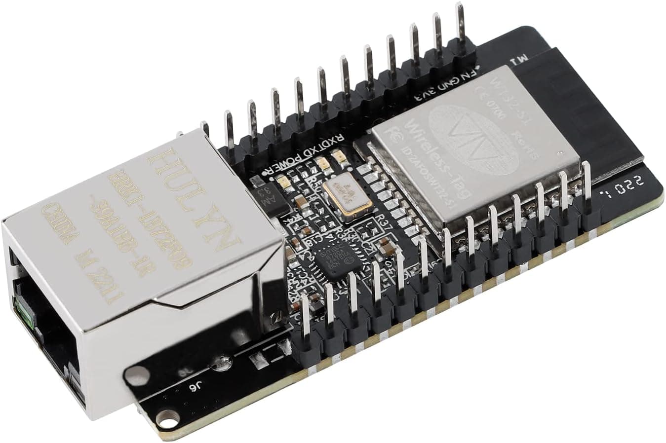
For this board you need a USB to TTL adapter.
The board has two sets of txd/rxd pins. With the board position as in the picture, the pins that worked for me were the two on the right hand side furthest from the Ethernet socket. You also need 5V and ground, both which are located on the left hand side close to the Ethernet outlet. These 4 pin need to be connected to the USB to TTL adapter.
In order to get this board into flash mode you have to short the IO0 pin, which is right next to the RTD pin you use. You run a wire from IO0 to ground. Thenyou apply power to the board. After power has been applied to the board you remove this wire and the board can be flashed from ESPHome.
I have the ESPHome addon installed on my HA controller. I plugged the board into my windows 11 laptop. I used the ESPhome addon Web Interface and selected the “+ NEW DEVICE” button. If you save the yaml below in a file name gpio-via-eth.yaml, you can then import it create the sensor and flash the code.
esphome:
  name: gpio-via-eth
  friendly_name: gpio-via-eth

esp32:
  #board: esp32dev
  board: esp-wrover-kit

  framework:
    type: esp-idf

# Enable logging
logger:
  level: INFO
#  level: DEBUG

# Enable Home Assistant API
api:
  encryption:
    key: !secret api_key

ota:
  platform: esphome
  password: !secret ota_password

ethernet:
  type: LAN8720
  mdc_pin: GPIO23
  mdio_pin: GPIO18
  clk_mode: GPIO0_IN
  phy_addr: 1
  power_pin: GPIO16

  # Optional manual IP
  manual_ip:
    static_ip: 192.168.10.121
    gateway: 192.168.10.2
    subnet: 255.255.255.0
    dns1: 192.168.10.2

# Enable Web server.
web_server:
  port: 80

binary_sensor:
  - platform: gpio
    pin:
      number: GPIO2
#      inverted: true
      mode:
        input: true
        pullup: true
    name: "Front Door"
    device_class: door

  - platform: gpio
    pin:
      number: GPIO4
#      inverted: true
      mode:
        input: true
        pullup: true
    name: "Back Door"
    device_class: door

  - platform: gpio
    pin:
      number: GPIO12
#      inverted: true
      mode:
        input: true
        pullup: true
    name: "Basement Door"
    device_class: door

  - platform: gpio
    pin:
      number: GPIO14
#      inverted: true
      mode:
        input: true
        pullup: true
    name: "Garage Door R"
    device_class: garage_door

  - platform: gpio
    pin:
      number: GPIO15
#      inverted: true
      mode:
        input: true
        pullup: true
    name: "Garage Door L"
    device_class: garage_door
I have 5 wired contact sensors that I needed to monitor. All the GPIO pins on the board are not appropriate for utilization with the internal pullup resister. I believe pins 35-39 generated an error. The pins I’ve selected worked. I also away use a static IP for my device. If you don’t want fixed IPs just comment out that section from the configuration.
As I previously stated the IO0 wire need to be connected to ground before you apply power to the board. Once power is applied you can remove the IO0 wire and the device is ready to flash.
One side of each contact sensors needs to be connected to the configured GPIO pins and the other side needs to be connected to ground.
With the above configuration you end up with a device named “gpio-via-eth” with 5 entities, 3 house doors and 2 garage doors.
This approach might have been alright if I could get the HA development team to add the routing capabilities I need in my setup. We’ll see that happens, but nothing yet.
Via ESP with WiFi
The next approach was to utilize a WiFi enabled ESP, which is how most of them are enabled. I had multiple sitting around and so I grabbed the Flutesan ESP32 Development board. This one is no longer available, but just about any other ESP32 development board should work. If you have the full size one like this one, it’ll most like expose all the same pins.
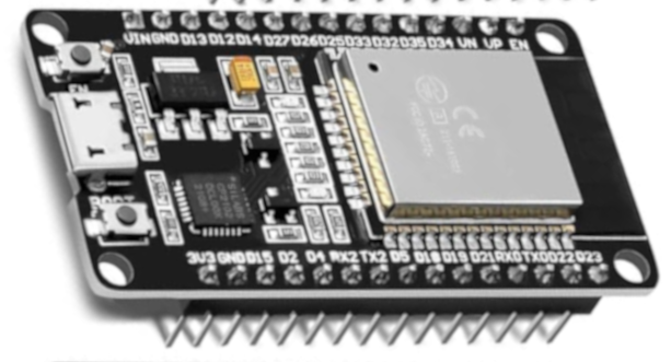
On this one the TTL is built in, so I just connected it to my laptop with an appropriate USB cable. I don’t remember doing anything special to get it into flash mode.
This was the configuration for this device:
esphome:
  name: gpio-via-wifi
  friendly_name: gpio-via-wifi

esp32:
  board: esp32dev
  framework:
    type: esp-idf

external_components:
  - source:
      type: git
      url: https://github.com/trombik/esphome-component-ping
      ref: main

# Enable logging
logger:

# Enable Home Assistant API
api:
  encryption:
    key: !secret api_key

ota:
  - platform: esphome
    password: !secret ota_password

wifi:
  ssid: !secret wifi_ssid
  password: !secret wifi_password
  manual_ip:
    static_ip: 192.168.10.202
    gateway: 192.168.10.2
    subnet: 255.255.255.0
    dns1: 192.168.10.2
  # Enable fallback hotspot (captive portal) in case wifi connection fails
  ap:
    ssid: "Gpio-Via-Wifi Fallback Hotspot"
    password: "Usecase2Config"

captive_portal:

# Enable Web server.
web_server:
  port: 80

binary_sensor:
  - platform: gpio
    pin:
      number: GPIO27
#      inverted: true
      mode:
        input: true
        pullup: true
    name: "Front Door"
    device_class: door

  - platform: gpio
    pin:
      number: GPIO26
#      inverted: true
      mode:
        input: true
        pullup: true
    name: "Back Door"
    device_class: door

  - platform: gpio
    pin:
      number: GPIO25
#      inverted: true
      mode:
        input: true
        pullup: true
    name: "Basement Door"
    device_class: door

  - platform: gpio
    pin:
      number: GPIO33
#      inverted: true
      mode:
        input: true
        pullup: true
    name: "Garage Door R"
    device_class: garage_door

  - platform: gpio
    pin:
      number: GPIO32
#      inverted: true
      mode:
        input: true
        pullup: true
    name: "Garage Door L"
    device_class: garage_door


sensor:
  - platform: ping
    setup_priority: -100
    update_interval: 30s
    ip_address: 8.8.8.8
    num_attempts: 2
    timeout: 1sec
    loss:
      name: Packet loss
#    latency:
#      name: Latency
#      accuracy_decimals: 3
Once flashed via the USB, subsequent updates can be done over wifi. When you flash and reboot the board, the device will be available to add in HA. The device is gpio-via-wifi, with 5 contact sensors and a ping sensor entities.
This solution requires me to add a wifi router to my battery backed up system. Also not optimal.
Via ESP with zigbee
I already had a lot of zigbee devices in my setup so I figured I give this approach a go. I liked this approach because it doesn’t require any additional hardware, beyond the ESP, being added to my battery backed up components. The device I utilized was the ESP32-C6-DevKitC-1-N8

ESPHome doesn’t currently support zigbee. It turns out that luar123 has done some amazing work, available on github. He currently has a PR in with ESPHome that is making it’s way though the process. Until that PR gets approved and integrated you have to utilize his code as an external component.
This device also has the TTL capabilities built in, so you just need to connect an appropriate USB cable. You have two choices for plugging into this device. While I successfully flashed via both USB sockets, it seemed in some cases the left side would not automatically go into flash mode, while the right side always did.
One thing about this device that you need to know, you can not have both zigbee and WiFi enabled together. I first configured this device like it was just a WiFi adapter and then I moved on to making the zigbee part work. As such I’ve left the WiFi configuration information in the file as comments. Here’s the configuration:
esphome:
  name: gpio-via-zigbee
  friendly_name: gpio-via-zigbee

esp32:
  board: esp32-c6-devkitc-1
  flash_size: 8MB
  partitions: partitions_zb.csv
  framework:
    type: esp-idf
    sdkconfig_options:
      CONFIG_ESPTOOLPY_FLASHSIZE_8MB: y

external_components:
  - source: github://luar123/zigbee_esphome
    components: [zigbee]

# Enable logging
logger:

# Enable Home Assistant API
#api:
#  encryption:
#    key: !secret api_key

#ota:
#  - platform: esphome
#    password: !secret ota_password

#wifi:
#  ssid: !secret wifi_ssid
#  password: !secret wifi_password
#  manual_ip:
#    static_ip: 192.168.10.203
#    gateway: 192.168.10.2
#    subnet: 255.255.255.0
#    dns1: 192.168.10.2

# Enable fallback hotspot (captive portal) in case wifi connection fails
#  ap:
#    ssid: "Gpio-Via-Wifi Fallback Hotspot"
#    password: "Use2Config"

#captive_portal:

# Enable Web server.
#web_server:
#  port: 80

binary_sensor:
  - platform: gpio
    name: "Front Door"
    device_class: door
    pin:
      number: GPIO18
#      inverted: true
      mode:
        input: true
        pullup: true
    on_state:
      then:
        - zigbee.report: zb


  - platform: gpio
    name: "Back Door"
    device_class: door
    pin:
      number: GPIO19
#      inverted: true
      mode:
        input: true
        pullup: true
    on_state:
      then:
        - zigbee.report: zb

  - platform: gpio
    name: "Basement Door"
    device_class: door
    pin:
      number: GPIO20
#      inverted: true
      mode:
        input: true
        pullup: true
    on_state:
      then:
        - zigbee.report: zb

  - platform: gpio
    name: "Garage Door L"
    device_class: garage_door
    pin:
      number: GPIO21
#      inverted: true
      mode:
        input: true
        pullup: true
    on_state:
      then:
        - zigbee.report: zb

  - platform: gpio
    name: "Garage Door R"
    device_class: garage_door
    pin:
      number: GPIO22
#      inverted: true
      mode:
        input: true
        pullup: true
    on_state:
      then:
        - zigbee.report: zb


zigbee:
  id: "zb"
  components: all
  on_join:
    then:
      - logger.log: "GPIO zigbee Joined network"
If you start with the wifi part, you will need to comment out the zigbee parts. Once you’ve flashed the zigbee code your only option to update the board or monitor the logs is via USB.
The configuration of this board requires you to include a partiton table for the zigbee code. A table that should work for you is include on github. I’ve include here to keep you from having to look for it.
otadata,  data, ota,     ,        0x2000,
phy_init, data, phy,     ,        0x1000,
app0,     app,  ota_0,   ,        0x1B0000,
app1,     app,  ota_1,   ,        0x1B0000,
nvs,      data, nvs,     ,        0x6D000,
zb_storage, data, fat,   , 16K,
zb_fct,     data, fat,   , 1K,
You have to save this file on you HA controller in the ESPHome directory. You need the Advanced SSH & Web Terminal addon installed on your controller.
You can use it to put this file in place. Once you start the terminal window you get in the right directory
cd config/esphome
Copy the partition records above and then in the terminal do the following
nano partitions_zb.csv
Paste the contents from above, and then enter the ctrl key and x key at the same time. You then enter the Y key followed by the enter/return key to save the file.
With this file in place, the configuration above and the device connected via USB, you should be able to flash the board.
To get the board to join your zigbee network you unplug it after it has been flashed. You go to your zigbee integration on the HA Web interface and use it to add a new device. I use ZHA, but this is code also works with zigbee2MQTT. You then plug the board in and the first thing it does is try to join a zigbee network. The new device will be called esphome gpio-via-zigbee and it will contain the 5 entities for the contact sensor.
Like the other board you connect one side of the contact sensor to the specified GPIO pins and the other size to ground.
With this board I found it to be very useful to have the device connected to my laptop. This way I could connect to the device via USB to see the logs.
When I first got the code running it would only report the events to HA at some time interval. As such I missed a lot of open and closed events. Using the logs, I could see the events happening in real-time. I then figured out that adding the on_state lines under each gpio sensor got the events passed to HA when they happened.