What’s it above
HA OS has limitation when it comes to routing traffic. It doesn’t support a redundant internet paths to provide backup internet access should your ISP go off line. It doesn’t support adding static routes. As such an operational implantation needs some augmentation to increase availability. I decided to make this a community guide as I know others would like to have enhanced networking within HA OS. Until HA does something in this area, this solution would be useful to others running a dedicated HA OS server. The device I utilized is a GL.iNet GL-AR300M16-Ext. If others have other ultra low alternatives I’d love that input. The average power consumption for this device is 1.5Watts.
Since Aug 2023 I’ve utilize HA to provide normal smart house security features. About a month ago I looked to move over to HA OS, as opposed to running HA supervised. My initial implementation is documented here.
While this implementation works fine, I felt there was room to reduce the power footprint by a couple of watts. The initial version implement with HA supervisor averaged power consumption was above 3 Watts. My first version on HA OS utilized around 8 Watts average, peaking a little above 10 Watts. The iteration document here utilizes an averages of 5 Watts, peaking a little below 8. The average watts required is important if you’re critical HA security capabilities are going to be backed up by battery power and it’s also good for the environment.
In this picture of my architecture the items in the green box are the ones handling the dual route.
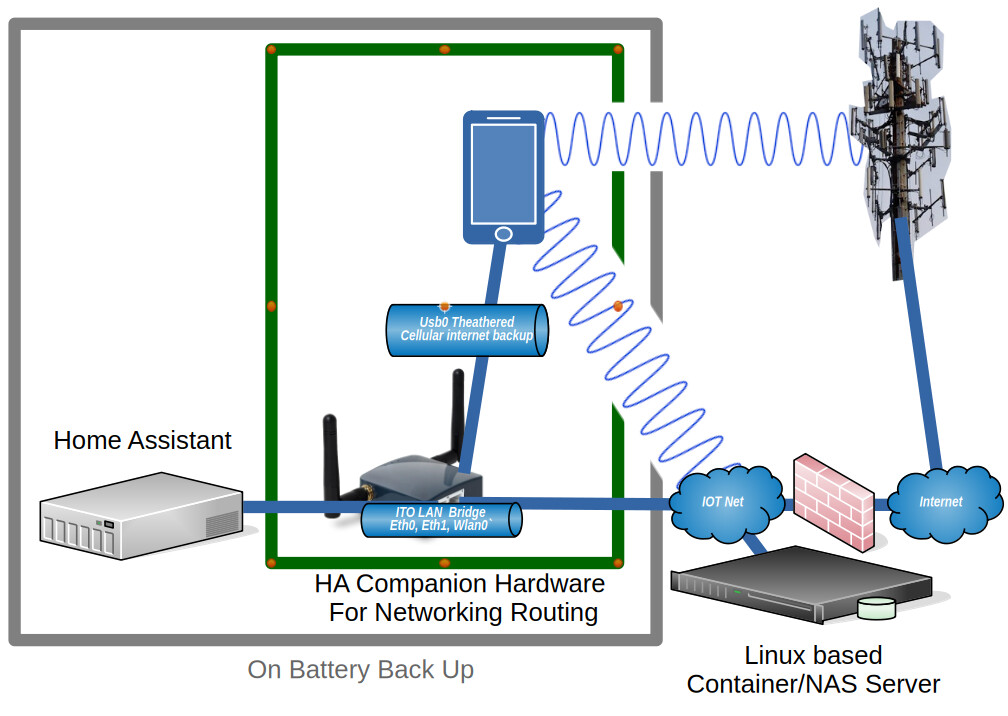
The networking works like this. The two NICs on the OpenWrt box are configured as a bridge. This allows HA to do it’s network scanning on the IOT network. The OpenWrt box is set up as the default route for HA. The cell phone tethers internet access via USB. The traffic that needs to be dual routed is traffic heading to the internet. The OpenWrt box sends all routable traffic from HA to the cell phone via the wan interface. The cell phone is connected to a WiFi access point on my IOT network. In this implantation I leave it to the cell phone to determine if the WiFi access is providing internet access. As long as the ISP is providing a good connection to the internet, the cell phone sends the traffic over WiFi and out the ISP route. When the phone determines the WiFi isn’t providing an internet route it shifts the traffic out over the cellular network.
While I use this for dual routing, I’ve read post where others were attempting to get static routes configured within HA OS. You can use this approach without the USB tethering and just set static routes in OpenWrt to get the traffic where it needs to go on your network.
I had two main requirements when starting this project. The first was to get onto HA OS without reducing my system capabilities. The second was to minimize the additional power draw added by any additional components. My system also has a requirement for GPIO access. From the last implantation, I migrated my GPIO requirements over to an ESP.
With the GPIO requirements off the plate, I was free to utilize a mini router that had a minimum of 2 network interfaces and 1 USB interface. The USB interface had to be capable of tethering a phone’s cellular internet, as this provides the backup internet access. The select platform also needs to run openwrt, as I knew it supported all my desired routing needs. I was also hoping to get reliable WiFi capablility with reasonable speed, but it was critical.
Based on what I could find on various SBCs & Routers power usage I settled on the GL.iNet GL-AR300M16. The router is pretty cheap and it meets the main requirements from above.
As a side note the GL.iNet routers run an OEM enhanced version of openwrt and will also run the community version. While working this project, I flashed multiple images as I was testing both from the vendor and from the openwrt community images. The latest version vendor version resulted in the root filesystem being locked read only on three separate occasions, each time requiring me to start over from scratch. Once I flashed the valid community version, I did not hit this issue. The OpenWrt community version is significantly newer than the latest OEM version. As such I’d recommend utilize the openwrt community version if you attempt this project.
I was hoping to utilize the WiFi on this router. The signal strength was strong and I was hopeful I would be able to use it in support of my system architecture. If it had worked well during my testing it could have provided a way to connect my WiFi enabled smart devices with HA. While I did have some initial test that showed about 40Mb data transfers, once I put the unit into position were it would live out it’s life, the data rate was below 10Mb. In addition when the WiFi was engaged it seemed to have a negative impacted on the tethered interface data rate. As such I decided not to utilize the WiFi.
Grabbing the community OpenWrt flash images
This link is good place to find the latest OpenWrt community version tied to the hardware platforms they support.
If you like you can run this project on the OEM OpenWrt version. If you want to move to the community version of OpenWrt you can grab the “Factory image” and “Sysupgrade image” files available from the openwrt page. This GL-AR300M16 router specific page provides links to the most recent stable versions for this router.
The Factor image resets the router disk space and put down a system recovery image. The recovery image is then used to install the full Sysupgrade image. The Sysupgrade image is also used to move from one version of OpenWrt to a newer version. The Factor image and the Sysupgrade image that I used were version 24.10.3:
openwrt-24.10.3-ath79-generic-glinet_gl-ar300m16-initramfs-kernel.bin
openwrt-24.10.3-ath79-generic-glinet_gl-ar300m16-squashfs-sysupgrade.bin
You can install the community Factory image directly from the OEM firmware update page. While this is true, I didn’t find any benefit in using that approach over just utilizing the UBOOT method to install the software. The OEM method for installing the image can only be done once. After which, you have to use the UBOOT method for a fresh install. So you might as well figure out how to use the UBOOT method from the start.
UBOOT install method
To install the image I utilized a Windows 11 laptop. You can utilize any machine that you have control of the network configuration for the install. In these instruction I will refer to the installing computer as the laptop.
To begin the install you first connect the LAN port of the router to the laptop. To get the router in UBOOT mode you hold in the reset button while applying power. Keep holding the button. The Power green light will come on solid and then the red WiFi light will flash 5 times. Finally the green configurable light will come on solid. At this point you release the reset button.
You have to configure the network setting on the laptop with the IP 192.168.1.2 and netmask of 255.255.255.0. No other network configuration fields need to be configured. You then connect to the luci web interface at the URL http://192.168.1.1/. The page presented allow you to identify the image file to be uploaded and flashed to the router. You will be uploading the Factory image (…kernel.bin) first. Once you start the update the lights will flash. You know the flashing is done once both of the green lights are solid again. You then need to power cycle the box. The box will take a while to boot. You will know it’s ready for the next step when the power light is solid green and the configuration light is flashing.
If the router is ready to move on you will be able to ping it at 192.168.1.1 and web surf to http://192.168.1.1/ again.
The web page at http://192.168.1.1 presents a login page. The user name is root and you leave the password blank to login.
You’ll have two notices at the top of the web page. The first instructing you to go and set the system password, don’t worry about this. The second one indicates you need to flash a complete image. Click the button on the second notification to go to firmware upgrade page and pick the Flash new image option. At the popup page select the squashfs-sysupgrade.bin image and upload it.
Take a break as it takes a while for the router to update. Both green lights will flash for a while, then the right one will be on solid and then go off, indicating the device is rebooting. The right green light will come back up blinking as the new image is finalized in the router. This will take a while.
Once the router is ready to move to the next step the power green light will be solid while the configure green light will be blinking. If the router is ready to move on, you will be able to ping it at 192.168.1.1 and web surf to http://192.168.1.1/ again.
Configuring the router
At this point you have the laptop connected to the LAN interface on the router and you need to connect the WAN interface to your home network. This enables the router to access the internet so you can add more packages.
When you access the web interface and login as root with a blank password you will have a notification instructing you to set a password. Click the button set the password and save it. You’ll get a notification that the password has changed. Logout and login with your new password.
Set the time zone
Under the System pull down menu you set the set time zone from System->System. You might also want to set the hostname. Save & Apply these changes.
Enable tethering
If you don’t need tethering you don’t need to do these steps. You can just hop down to the Bridge steps. If you don’t do these steps you may have an issue assigning eth1 to the bridge because it’s currently assigned to the wan. I don’t know. But I know if it’s an issue you candelete the wan and wan6 interfaces and then the eth1 interface will be free to assign to the bridge.
If you might use tethering then It’s best to get the tether interface working at this point, so ssh into the router at 192.168.1.1 and log in as user root with the password you just configured.
To enable tethering we need to add some modules. At the ssh command prompt issue the following command to see what interfaces currently exist:
ifconfig -a
Keep track of this list so you can determine if a new interface gets added after the next step. Enter these command to install the packages that enable the route to detect the Phone’s internet tether:
opkg update
opkg install kmod-usb-net-rndis kmod-usb-net-cdc-ncm
If the opkg update fails to download the package list, but you can ping google.com, the clock is probably not set to the correct time. The clock updated automatically before I ever took any corrective action. So if you wait a couple of minutes it should start working.
The above two packages are for android phones, different modules required for iPhones.
Plug the phone into the USB port and enable tethering. Use the ifconfig -a command again to look for the presence of a new device. For me the new device was usb0. It’s possible that it could be something different based on the phone you use. If no new interface shows up you might need to install additional modules. This web page provides full details.
From this point forward you will make changes and only saving them. Do NOT “Save & Apply” Any changes until the end.
Back on the web interface we can now change the wan and wan6 interfaces to use the new device. Under Network->interface edit both the wan and wan6. On the general tab you change the device from eth1 to usb0 (or whatever your new device is). You save the change. and then Save it again. Do NOT click the Save & Apply until instruction tell you to Save & Apply the changes. At which point all the changes will be applied together.
Bridge the two Network Interfaces
You now move eth1 over to the lan interface. So on the Devices tab you click configure for “br-lan”. The Bridge port field is a pull down that you want to connect with both eth0 and eth1. Save the change.
Back on the Interface tab you edit the lan interface and configured the IPv4 address. This should be changed to the address you want the device to use on your network. Make sure you enter a good address for your network and you remember it or you’ll be starting over from the top with a UBOOT install.
Over on the DHCP server tab you check ignore interface, as you don’t want this router handing out ip addresses for your home network. Save it and then Save & Apply these changes.
Finally click the apply unchecked button.
Now change the laptop back to utilizing DHCP on the interface connected to the router. If all goes well the laptop should be assigned an ip address from your home network. I’ve been through multiple times. In some cases an IP was immediately assigned. In other case an IP didn’t get assigned. Once I power cycled the router and then things worked. Another time I just waited a minute, disconnected the network cable from my laptop, waited a few seconds and plugged it back in and my laptop was assigned an appropriate address.
ssh and web access
To access the router’s web interface you need to update the url in your browser to the IP you assigned to the router. You’ll have to login again.
The service ssh is enabled on all interfaces by default. I’d recommend you restrict the access to only the LAN interface. Select the System->Administration option. Click ssh access tab and change the Interface field to lan, followed by save.
You should require the router be configured by HTTPS. Move over to the HTTP(S) Access tab, click Redirect to HTTPS and then Save & Apply.
You’ll need to refresh your web browser page so you’re redirected over to HTTPS to continue.
WiFi
WiFi will be disabled so if you don’t need it you can leave it off. If you want to use the WiFi then do these steps. You enable it off the Network-> Wireless page.
Select the edit option for the disabled entry.
On the General Setup tab at the bottom of the page enter your desired ESSID.
Select the wifi security tab at the bottom of the page and select an encryption method.
Enter the network passphrase you want to use in the key field.
At the top of the page click the enable button.
WiFi should be enabled now.
The button you used to enable WiFi can now be used to Disable WiFi if you decide it’s not needed.
Static routes
The last step is to add any addition static routes for the lan interface if you have other lan segments on your home net that have reason to communicate with Home Assistant.
Select the Network->Routing pulldown and add your various static routes. In most cases you will be adding unicast static routes. Save & Apply the routes.
To give HA the ability to determine if the connection to the ISP functioning, I include a static route to Google’s DNS 8.8.4.4 that routes out my ISP interface. Then I set up a ping tracker to this address. Failure to ping 8.8.4.4 indicates the ISP is down and so traffic is being routed out over the cellular network.
Disable IPv6
I don’t use IPv6 on my network, so I disabled it via the following commands at the ssh command prompt
uci set network.lan.ipv6=0
uci set network.wan.ipv6=0
uci set network.lan.delegate='0'
uci commit network
uci -q delete dhcp.lan.dhcpv6
uci -q delete dhcp.lan.ra
uci commit dhcp
/etc/init.d/odhcpd disable
/etc/init.d/odhcpd stop
uci -q delete network.globals.ula_prefix
uci commit network
/etc/init.d/network restart