Guidance for 2-wire DC fan control

Can someone point me to some tips on creating a fan controller for DC 2-wire fans?

I do see a lot of examples with 3 & 4 wire DC fans, but I haven’t found one for 2-wire fans.

I am looking to control a 24VDC 3 amp inline duct fan. These are often used as marine bilge blowers. 4" In-Line Bilge Blower Fan - SeaFresh Marine - An Authorized SEAFLO Dealer

You need a h-bridge controller - here is an example from Aliexpress:

https://www.aliexpress.com/item/1005005266530676.html

And there is a H-Bridge component in ESPHome:

What do you want to do with it ??

If you only want to turn it On or Off then use a relay, speed control can be done with a Mosfet and PWM and the H-Bridge that Daryl suggested will give you reversal of direction of air flow (if the blower supports that)

Use case will be ventilating a custom converted van for comfortable sleeping.

I want on/off with speed and direction control.

It looks like the L298N modules have both H-Bridge & PMW features. Are you recommending a separate MOSFET?

Your fan is 3A and the L298 has a continuous load rating of 2 A so you will need a different H-Bridge module with a higher current rating.

At least 6A. The cold start current of the motor will be higher. I used something like this H-Bridge for a Halloween prop where a battery powered drill motor was used to twitch a dragon’s tail.

2 Likes

Most of the boards on that link have power ratings around 150-170W, which will be suitable for your fans, with overhead that Steve recommends.

Thank you @gaz99 @stevemann @zoogara, I will give the 10amp one Steve posted a try.

Hey @stevemann , I’ve just bought the board you suggested in attempt to control some 80w DC fans and struggling with it bogging down when I set the speed over 89%.

As the board doesn’t have 2 directional pins, I’ve set it up as an gpio for the directional and pwm for the pwm but it just doesn’t seem happy. I also get different speed behaviours when running the different directions.

This is my esphome config. Could you possibly give me some pointers or share the code you used for your setup? Thanks very much!

output:
  - platform: esp8266_pwm
    pin: D4
    id: fire_fan_pwm
    frequency: 25000 Hz

  - platform: gpio
    id: motor_reverse_pin
    #frequency: 1 Hz
    pin: GPIO4

  - platform: speed
    id: control2
    name: control2
    output: fire_fan_pwm
    restore_mode: RESTORE_DEFAULT_OFF
    #speed_count: 10
    direction_output: motor_reverse_pin

You made me go into Github to find my old projects.
The only place that I used the motor control was in an Arduino sketch:

/*
  HG7881_Motor_Driver_Example - Arduino sketch

  This example shows how to drive a motor with using HG7881 (L9110) Dual
  Channel Motor Driver Module.  For simplicity, this example shows how to
  drive a single motor.  Both channels work the same way.

*/

#define SKETCH "HBridgeTest.ino"
#define MOTOR_PWM D1          // Motor PWM Speed
#define MOTOR_DIR D2          // Motor Direction

// the actual values for "fast" and "slow" depend on the motor
#define PWM_SLOW 500           // arbitrary slow speed PWM duty cycle
#define PWM_FAST 1023          // arbitrary fast speed PWM duty cycle
#define DIR_DELAY 1000        // brief delay for abrupt motor changes

void stopMotors() {
  digitalWrite( MOTOR_DIR, LOW );
  digitalWrite( MOTOR_PWM, LOW );
  delay( DIR_DELAY );
}


// ------------ setup() ------------
void setup()
{
  Serial.begin( 115200 );
  Serial.println();
  Serial.println(SKETCH);
  pinMode( MOTOR_DIR, OUTPUT );
  pinMode( MOTOR_PWM, OUTPUT );
  stopMotors();
}


// ------------ loop() ------------
void loop()
{
  bool isValidInput;

  // draw a menu on the serial port
  Serial.println(F( "-----------------------------" ));
  Serial.println(F( "MENU:" ));
  Serial.println(F( "1) Forward" ));
  Serial.println(F( "2) Reverse" ));
  Serial.println(F( "3) Fast forward" ));
  Serial.println(F( "4) Forward" ));
  Serial.println(F( "5) Soft stop (coast)" ));
  Serial.println(F( "6) Reverse" ));
  Serial.println(F( "7) Fast reverse" ));
  Serial.println(F( "8) Hard stop (brake)" ));
  Serial.println(F( "-----------------------------" ));

  do {
    byte c;
    // get the next character from the serial port
    Serial.print( "?" );
    while ( !Serial.available() ) ;
    c = Serial.read();

    switch ( c )
    {
      case '1':                                   // Fast forward
        Serial.println(F("H-L..."));
        stopMotors();                             // Stop motors briefly before abrupt changes
        digitalWrite( MOTOR_DIR, HIGH );          // direction = forward
        analogWrite( MOTOR_PWM, LOW);
        isValidInput = true;
        break;

      case '2':                                   // Fast forward
        Serial.println(F("L-H..."));
        stopMotors();                             // Stop motors briefly before abrupt changes
        digitalWrite( MOTOR_DIR, LOW );          // direction = forward
        analogWrite( MOTOR_PWM, HIGH);
        isValidInput = true;
        break;

      case '3':                                   // Fast forward
        Serial.println(F("Fast forward..."));
        stopMotors();                             // Stop motors briefly before abrupt changes
        digitalWrite( MOTOR_DIR, HIGH );          // direction = forward
        analogWrite( MOTOR_PWM, PWM_FAST );
        isValidInput = true;
        break;

      case '4':                                   // 2= Forward
        Serial.println( "Forward..." );
        stopMotors();
        digitalWrite( MOTOR_DIR, HIGH );          // direction = forward
        analogWrite( MOTOR_PWM, PWM_SLOW ); // PWM speed = slow
        isValidInput = true;
        break;

      case '5':                                   // 3= Soft stop (preferred)
        Serial.println( "Soft stop (coast)..." );
        stopMotors();
        isValidInput = true;
        break;

      case '6':                                   // 4) Reverse
        Serial.println( "Fast forward..." );
        stopMotors();
        digitalWrite( MOTOR_DIR, LOW );           // direction = reverse
        analogWrite( MOTOR_PWM, PWM_SLOW );       // PWM speed = slow
        isValidInput = true;
        break;

      case '7':                                   // 5= Fast reverse
        Serial.println( "Fast forward..." );
        digitalWrite( MOTOR_DIR, LOW );           // direction = reverse
        analogWrite( MOTOR_PWM, PWM_FAST );       // PWM speed = fast
        isValidInput = true;
        break;

      case '8':                                   // 6= Hard stop (use with caution)
        Serial.println( "Hard stop (brake)..." );
        digitalWrite( MOTOR_DIR, HIGH );
        digitalWrite( MOTOR_PWM, HIGH );
        isValidInput = true;
        break;

      default:
        // wrong character! display the menu again!
        isValidInput = false;
        break;
    }
  } while ( isValidInput == true );
}

Last year, I had a high-torque servo motor that would turn a chair where a skeleton was seated. This was controlled with ESPHome:

# This is the chair servo for the 2023 Halloween props.

# PWM Output is on GPIO2
# A button can be added to GPIO0

substitutions:
  device_name: freds-chair
  friendly_name: freds_chair

packages:
  wifi: !include common/wifi.yaml
  device_base: !include common/esp8266.yaml

esphome:
  on_boot:
    priority: -100.0
    then:
      - delay: 500ms
      - script.execute: look_left
      - delay: 2000ms
      - script.execute: look_right
      - delay: 2000ms
      - script.execute: move_to_zero

######################################################

output:
  - platform: esp8266_pwm
    id: pwm_output
    pin: 2
    frequency: 50 Hz

servo:
  - id: servo_signal
    output: pwm_output
    restore: true

number:
  - platform: template
    name: ${friendly_name} servo control
    min_value: -100
    max_value: 100
    step: 1
    set_action:
      then:
        - servo.write:
            id: servo_signal
            level: !lambda 'return x / 100.0;'
            
button:
  - platform: template
    name: ${friendly_name} zero
    icon: "mdi:liquid-spot"
    on_press:
      then:
        - script.execute: move_to_zero

  - platform: template
    name: ${friendly_name} look left
    icon: "mdi:liquid-spot"
    on_press:
      then:
        - script.execute: look_left

  - platform: template
    name: ${friendly_name} look right
    icon: "mdi:liquid-spot"
    on_press:
      then:
        - script.execute: look_right


# trigger the look_left script when the "binary_sensor.prize_delivered_prize_delivered_switch" entity changes its state.
binary_sensor:
  - platform: homeassistant
    entity_id: binary_sensor.prize_delivered_prize_delivered_switch
    name: ${friendly_name} Prize Delivered
    on_release:
      then:
        - script.execute: look_left
        - delay: 6s
        - script.execute: look_right
        - delay: 300s
        - script.execute: move_to_zero


#Pressing the button on GPIO0 returns the servo to zero.
#binary_sensor:
#  - platform: gpio
#    name: ${friendly_name} action_button
#    pin:
#      number: 0
#      mode: input_pullup
#      inverted: True
#    id: button_fire
#    on_press:
#      then:
#        - script.execute: move_to_zero
    

script:
  - id: move_to_zero
    then:
      - servo.write:
          id: servo_signal
          level: 0%

  - id: look_left
    then:
      - servo.write:
          id: servo_signal
          level: -100%

  - id: look_right
    then:
      - servo.write:
          id: servo_signal
          level: 100%


I would suspect the PWM frequency. From my limited experience, 25kHz seems high. What do the controller specs say?

Ah legend! Thanks for coming back to me.

Looking at your Arduino code, you’re pulling the direction high and low which I believe is as I’m doing.

Then you’re sending a pwm for a fast paced and slow which whilst mine is spread over 0 to 100 percent, it’s basically the same.

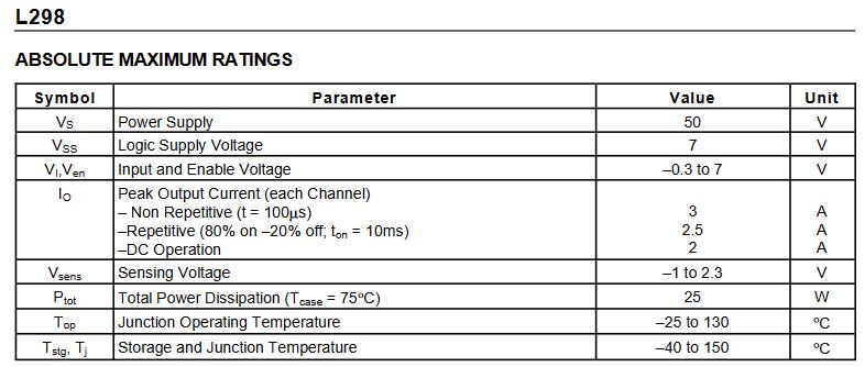
I did wonder about the frequency, anything lower than 20k and I get the expected digital noise from the motor which I’ve come to learn is expected at those lower ends. I must say I’m not sure what the specs of the board are, I’m not overly sure where to look to get them.

I do find it odd that the speed reacts differently on when changing ghe direction of the motor and keeping the frequency the same.

I’m just a little lost on the next steps to make it work.

I can think of several reasons for this. I would guess that the shape of the PWM waveform isn’t symmetrical. I recall that when working with a prop a few years ago, reverse wasn’t as fast as forward. But nothing was overheating and the speed did not have to be symmetrical.

Ah ok, much the same as the OP this is for fan control so I wanted as much throughput both ways.

So you suggesting that when the direction is set, it’s modifying the waveform further to achieve the reversed polarity?

I guess I really need to be using 2 relays to flip to polarity after the output of the board to maintain the same speeds then?

Do you have any ideas why it would be bogging down after 89%? I have 12v input to the board and on the output it gets up to 10.9v on the motor output at 89% then gradually drops back to 7v the further past 87% that I get?

I would first control specs of that 12V PSU…

How do you mean? Not quite sure I follow. It’s a 12v 44Amp if that helps? Thanks!

Should be sufficient… :sweat_smile:

Ah! I see, you were wondering if it was capable of the load. Yeah, I did think that too, the fan is supposedly rated at 80w 12v so around 6.6amps, however it’s just the high 6 amps for the hard start then levels off at around 3amps when up to speed. I was using a 5amp 12v supply initially when using a a manual speed controller pwm to DC and it was fine as long as I didn’t start it at 100%.

I switched out to this beast of a PSU before I posted as I wondered if it was to do with it being incapable of the load in this configuration.

I want to be able to control the fans with home assistant as I want them be engaging automatically based on the environment temp. I may just go with some relays to switch the polarity off the output. A bit more involved in terms of components but I really want to have the flexibility of full pelt in both directions.

Not intentionally. I doubt that the builder of the bord was concerned with matching the power mosfets. The forward mosfet could be a little faster than the reverse mosfet. The Vgs is not likely the same for the mosfets- one may turn on earlier than the others.

In the H-Bridge, in the forward direction, the PWM signal turns on Q1 and Q4. Remember that the PWM signal is a square wave and the speed of the motor is determined by the PWM Duty Cycle:

duty

If you replace the H-bridge with a DPDT relay, you would effectively have a 100% duty cycle. If the forward and reverse performance of the fan is different using a relay, or switches, the issue is with your fan.

I just had another thought. Swap the +/- wires from the motor. If the directional anomaly doesn’t change, then the motor is the problem.

That’s the first thing to verify when you have voltage going down while increasing power. Another thing I could think is that those motor drivers usually have quite big voltage drop. Maybe your motor is not happy with that 10V at high pwm. If you are using atx PSU there is usually trimpot inside to increase voltage little bit.
Or you could use those 2-ch relay modules, not increasing component count.

So after a fair amount of messing around but refusing to give up, I actually worked out a solution.

In the lower end speeds I would get the audible noise on the motor with any frequencies from 0-20khz so I thought bumping the frequency to 25k+ was the solution. Sure it solved the noice but I’d constantly have the drop off in the higher speeds.

For some ignorant reason, I tried the lower frequencies with the lower speeds and didn’t think to try insanely low frequencies in the high end until I made a mistake in my code which set the frequency to the speed step percent so 100% also became 100hz, all at the same time, instead of trying to be nice to my power supply and setup and easy the power up using the slider in HA, I hit the power button causing a hard start at 100%.

What followed was a full speed, full 12v, no noise, no interference smooth run of the fan. I played around a little and backed the speed off until I got the digital sound interference from the motor and noted that as 70%, and my spot to switch over to the much higher frequencies. Now I just have a simple if speed setting below 70%, use 25khz, else use 100hz and it all works pretty much perfectly.

I want to optimise it a little more as I’ve played around with calculating the frequency based on the speed percent as I’m still getting a little hopping around on the speed at the 70% switch over but it’s working almost perfectly with the directional options too.

Once I have it sat nicely, I’ll post the esphome yank config for others if ever useful.

Thanks @stevemann and @Karosm for you input and help. You both ultimately steered me to a solution! :+1::+1::muscle::muscle:

I’ll post the tidied up code over the coming days. :+1::+1: