I did it, but first time I’ve put just the ha-neopool-mqtt-package.yaml.
Now I’ve saved all tree files in the Packages folder.
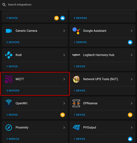
In MQTT I can see 52 entity, so now is integrated.
Just to know: to display the layout you shown at the biginning of this tread, I have to create it by my self (use mushroom, layout-card and so on)?
HA NeoPool MQTT: integration of Tasmota NeoPool (for Sugar Valley, Hayward/Aquarite, Bayrol devices)
You need to put only one file, the one referenced in the packages section in the config.yml file:
packages:
    neopool: !include packages/ha-neopool-mqtt-package.yaml
This tells HA to pull the ha-neopool-mqtt-package.yaml as it was a section of the config.yaml file. You don’t need any other file, so delete the other two.
You need to install all the addons mentioned, then put the lovelace file content in your lovelace file, in raw edit mode.
RS485 is a serial bus, true but this is only the physical layer.
The logical layer (Mobus RTU protocol) on top of this RS485 serial bus here does not allow several different clients (Display, Tasmota, also called Modbus-Master) on the same server (here it is the Sugar Valley [SV] system, also called Modbus-Slave).
On Modbus RTU you can connect one client (Modbus-Master) on several server (Modbus-Slave) not vice versa.
For me, a repeater is just an amplifier that refreshes signals that may be too weak to connect more than one device to an RS485 interface. But it doesn’t help here because the problem is a collision at logical Modbus level. You are connecting several clients (master) to one server (slave) and this does not work.
Let’s see what happens at Modbus level:
- Display is constantly sending Modbus commands to read registers. SV now sends a response to the request on the RS485 bus.
- If a second device (Tasmota) now sends other commands to SV, this disturbs the RTU Modbus command sequence and a logical protocol collision occurs
Try it out, connect a Tasmota and Display to the same RS485 port. Tasmota will only show garbage or nothing at all and the display will show an error message.
This chip (it’s a interface card) is missing for all devices. It comes together with the probe when you buy a PH or ORP set and you have to install it in the proper slot. The interface card for PH and ORP are the same, this is just a level adjustment.
Unfortunaley not, the COND probe has to be connect to the COND connectors and does not need an extra interface card (chip) as it is normaly on-board (or not, then the board does not support COND).
I’m not talking about the card, but the component next to where you put the card (you see it here, highlighted in red):
Someone told me it’s doable: you solder that component (it’s the same as the one next to ph and ORP connectors) then you set some registries that allow a factory menu to appear where you can choose the system mode, you choose Aquascenic and the COND interface will be enabled. Then you buy the COND kit (card and probe) and it should work.
Modbus RTU allows for one master and more slaves. The problem is at the physical layer because you have only one port in his system. Those repeaters should manage not only signal refresh but (I would imagine) also the fact that only one slave communicates at the same time, at least I would have designed it that way. In any case, conflicts happen also when you have multiple ports, I don’t think there’s a way in the protocol to prevent conflicts (a tx pin on the bus, a token passing system in the protocol, etc.).
If it was like you said, why did they create these repeaters? I see them used in many RS485 projects to “duplicate” the single port.
That’s for the CD probe and needs also a level card on the connector left to the red marked. The three interfaces CD, RX and PH are all structured in the same way.
The COND sensor has to be connected (marked yellow)
Sorry, but that’s not true.
exactly, so if I solder that missing chip (in my system the red component is not there) and I buy the COND kit, I put the card in the CD connector, I plug the probe and then I modify the registries to select another model, and it should work. But I won’t try during warranty period. ![]()
That’s true, but the display and tasmota is a master and SV is a slave.
before trying neopool I tried to use another solution, and debugging the communication there were indeed conflicts. tell me, at protocol level (Modbus RTU) what is the mechanism that prevents a slave to communicate if another one is communicating? It should be in the spec.
That’s Modbus terminology, it doesn’t change the fact that there’s no mechanism to prevent two slaves to communicate at the same time. But if I’m wrong, I’ll be glad to read where in the spec there’s the conflict management. ![]()
I think this is going nowhere, just give it a try, it doesn’t work.
Oh no, I think I understand what you’re saying now: there are two masters, and that’s not possible. That means there are separate modbus rtu chains in systems with more ports (like mine) and SV is a slave on all of them, and in his case only one, and there can’t be two masters on that port.
Got it now. ![]()
Good Morning and Happy Easter to every body!
Update:
Connect direct the AtomS3 to Display port (Display for a moment is not connect), these are the data view:
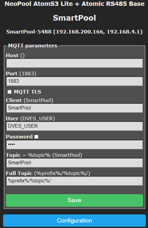
HA configurated, follow Alex instruction, but unfortunatelly I cannot see the entity working:
Thank you Norbert,
You have clarify me why the repeater don’t work.
So, now I will change the circuit. I put a small switch that cuts off power to the display and activates the Tasmota and vice versa.
It’s not a beautiful system, but as long as it’s functional.
You have not specified a MQTT server within Tasmota (MQTT parameter “Host” is empty)
Like Norbert said, you did not configure the MQTT server in Tasmota. Likewise, you also need to configure the MQTT integration in HA. All communication between SmartPool and HA is done via an MQTT broker.
Did you install an MQTT broker? ![]()
MQTT broker is install in my HA, configured with mine Tesla.
I have insert in the host the IP address of my HA, but still the same, entity didn’t work.


