Hack: Turning a 433MHz thermometer into a light meter

BACKGROUND
There are quite many cheap 433MHz temperature and humidity sensors out in market but hard to find a cheap light meter that would provide illumination measurements, not only a triggering.

THE OBJECTIVE
To modify an existing temperature and hygrometer sensor by soldering off the thermistor and replacing it by a light dependent resistor (LDR). For such endeavour I bough a Nexa NBA-001.

BILL OF MATERIAL
1pc Nexa NBA-001
1pc Photo resistor - Light Dependent Resistor (LDR)
1pc 7.5KOhms resistor

HANDS ON
On the bottom right side of the circuit board you see the target, the blue thermistor we need to replace by a LDR.

The challenge here is to replace the thermistor by a LDR component that is to oscillate in the same range as the thermistor, in other words, to have the same impedance. After some calculations and trial-error exercises I found that I had to put a 7.5KOhms resistor in series with the LDR. By doing so, I do not get out-of-range reading on the display of the NEXA NBA-001.

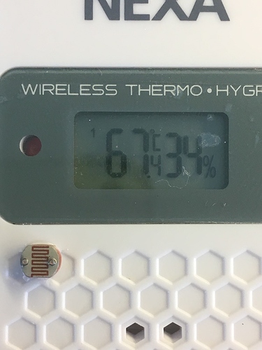
To not complicate the post with the maths behind it, what I did was to set the device on complete light (the best is direct sun light) to complete darkness. I got readings ranging from -72C to +72C.

And here is the result:

The next was to convert those reading to Lux. For that I made use of a cheap light meter (lux) I bough in eBay and the e-Exponential regression calculator found here.

This is the result of what I got but you should create your own one for best accuracy.

This is the snippet I use to convert the values to lux:

sensor:
  - platform: rfxtrx
    automatic_add: False
    devices:
      0a5207002f0e0291270289:
        name: LumenHygro
        data_type:
          - Humidity
  - platform: template
    sensors:
      lux_value:
        value_template: >
          {% if states.sensor.lumenhygro_humidity.attributes.Temperature > 0 %}
            {{ (0.02755061*e**(0.142984576*(states.sensor.lumenhygro_humidity.attributes.Temperature))) | round(0) }}
          {% else %}
            {% if states.sensor.lumenhygro_humidity.attributes.Temperature <= 0 %}
              {{ 0 }}
            {% endif %}
          {% endif %}
        friendly_name: "Illuminance"
        unit_of_measurement: "lx"
        device_class: illuminance

KNOWN PROBLEMS/LIMITATIONS

  • This Nexa device compensates the Hygrometer value for “temperature”. This means that low luminosity levels give negative “temperature” values and so the Nexa device compensates the Hygrometer values accordingly. This means that the Hygrometer is not reliable unless a regression formula is set to void the compensation.
  • It seems to me that lux measurement is ideal for bright environments however I do not find it useful in dim or low illuminated environments since the tendency is to give cero lux or very low lux values and so loosing resolution. In other words, at night, when using artificial light at home, I easily get cero or very low lux values even when it is not completely dark. This is the behaviour I find using the cheap lux meter I bought in eBay. Is this the expected behaviour? Any hint?
4 Likes

Hi,

I have a similar setup however I’ve replaced the humidity sensor with LDR, not the temperature sensor in order to have 0-100% scale which is easier to deal with :slight_smile:

Didn’t have to use a resistor either as it doesn’t generate out of scale values (it is not placed in direct sun or artificial light and the variation interval is 20 to 98%; when using artificial light the reading is above 90%).

I think that LDR sensors always need calibration due to different tolerances used by manufacturers. Don’t know how to identify high/low build quality batches.

For the calibration I’ve monitored the values read by the station for several days and found that around 60% is the right threshold in order to turn on the lights (also using sun state as condition).

For light measurement in every room I’m using a LDR attached to ADC pin of ESP8266 (with threshold at 50/1024~5% so it immediately sends value changes to MQTT). However, for the bathroom I went for the option of placing the LDR inside the weather station (regardles of the 30 s delay between reads) as fiddling with wires in the bathroom, even at 5 V, isn’t quite the definition of safety.

Also using one for monitoring the status led on the washing machine.

1 Like

Interesting. As far as I know, the humidity is measured by changes on frequency in that sense, the humidity sensor is a sort of capacitor that changes its capacitance with humidity. On the other hand, the thermistor is just a resistor that changes its impedance with the temperature. The LDR is a resistor that changes its impedance with the light therefore I replaced the thermistor with a LDR. As I mention in my post, my device compensates humidity readings with changes in temperature but not the other way around therefore another reason I went for the thermistor. Stil, interesting to see you got it to work! :slight_smile:

Do you have a link to the components you used at all?

Weather station (works fine in the fridge/bathroom/probably with some insulation also outside, for regular hum&temp monitoring):
https://www.aliexpress.com/item/Digoo-DG-R8H-R8H-433MHz-Wireless-Digital-Hygrometer-Thermometer-Weather-Station-Outdoor-Sensor-for-TH11300-TH8380/32845484171.html

For LDR simply order some cheap sensors:

If planning to use LDR with NodeMCU ADC pin to monitor light intensity see these (don’t use the ones with 4 pins as the Analog pin is not connected properly):

Hi @Petrica, How do you read the 433 data from this unit?

Hi @baz123,

I use RFLink (rflink.nl). It requires an Arduino Mega and a 433 Mhz emitter and/or receiver with the firmware from the mentioned site.
This is the most comprehensive 433 Mhz solution (can receive from most PIR, open door, water leak or smoke sensors; can also control 220 V sockets, relays, etc), however not the easiest to use or most options filled (such as the ones that are MQTT enabled).

Hi @Petrica, thanks. I have gone full circle. I looked at this a while back but thought it overly complicated. Guess I will have to look at this further.

Cheers.

Well, the flashing part is quite ok.

Flasher is a Windows executable which is included in the archive downloaded, then is the loading of the firmware part and this is it; no alteration of the code is needed and no chance to screw it up or to turn the whole neighborhood into flames (although I’m unsure about last part, at least I can say that it won’t hide the remote or leave the toilet seat up :slight_smile: ).

The HA integration is slightly more difficult as it requires running the component in debug mode for a while to get the IDs of the devices identified, however it is not rocket science either.

1 Like

Take a look at the “RFXtrx433XL USB 433.92MHz” or its little bro “FRXtrx433E” at http://www.rfxcom.com. I have the little brother and I am quite happy with it. It integrates with HA very easily. Actually the snipped above is for this platform (platform: rfxtrx).

100 Euros! I think the RFLink stuff is expensive and it is half the price :smiley:.

Hi,

If ordering a pre-assembled board from their site it is quite expensive and moreover: where’s the fun in it? :slight_smile:

However, you can order the Arduino Mega board, the 433 Mhz emitter and receiver separately (90%+ of the Arduino boards are Chinese stuff anyway) and the price should be lower than 10 EUR.

A way of going cheap is using pilight and their homemade solution based on the attiny84 with $2 433MHz receiver and transmitter. Pilight can be integrated with HA and it works like charm.

1 Like