Haier Air Conditioner

Hi!!!
I did some more tests and I found out that my ground was not connected!!

Here I update the frames. Now the structure makes more sense.
https://drive.google.com/drive/folders/1cQpStGslVXtKyNsSP_BV0ZW_kcq9yRuF?usp=sharing

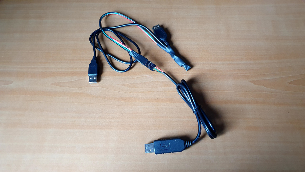
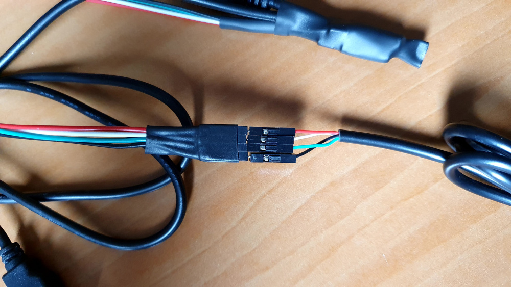
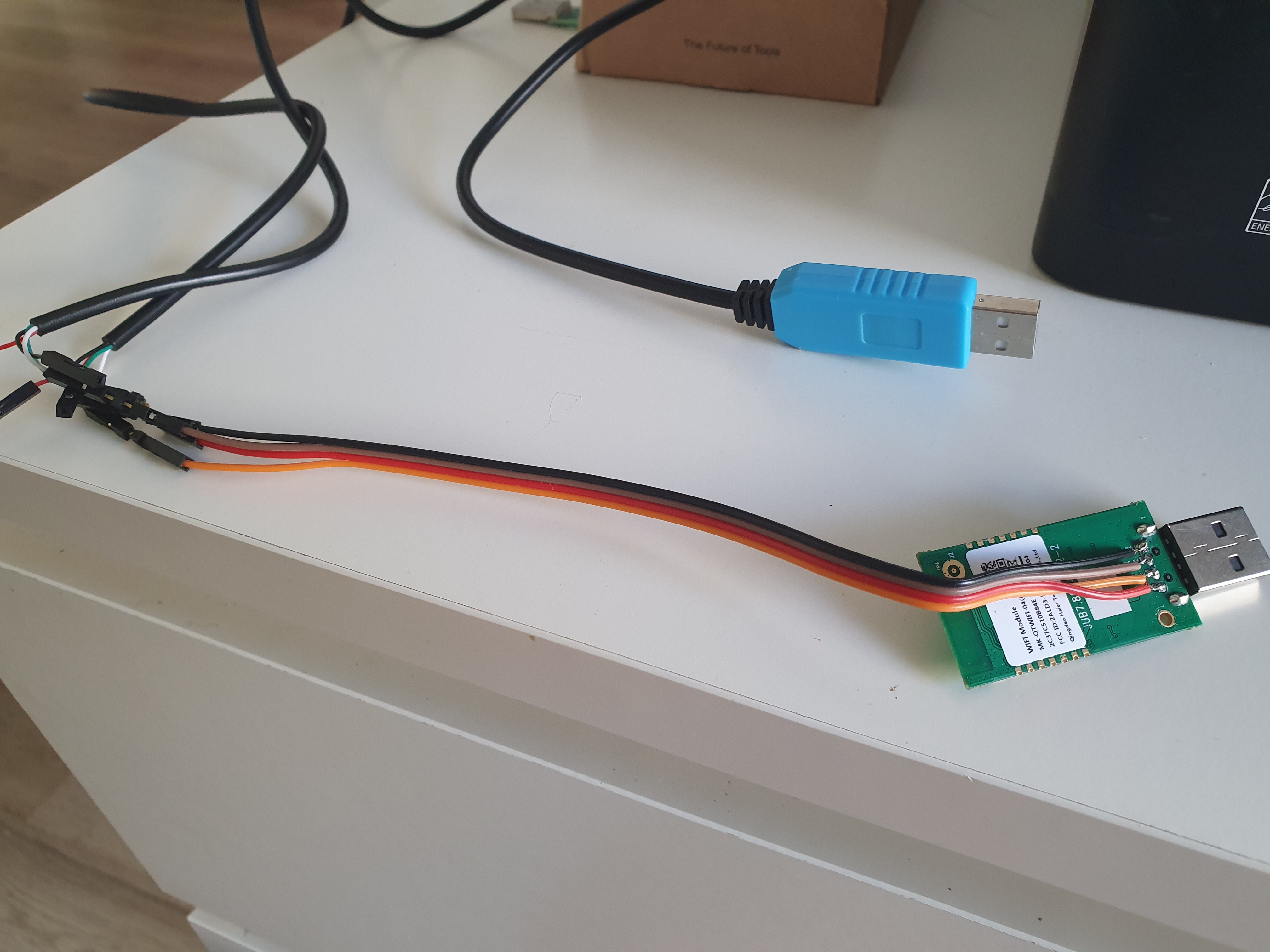
After that, I send some frames from my laptop with FTDI conversor to the HAIER uart and worked!!
ON command: FF FF 0C 40 00 00 00 00 00 01 5D 01 00 01 AC BD FB
OFF command: FF FF 0C 40 00 00 00 00 00 01 5D 01 00 00 AB 7D 3A
Setpoint 25: FF FF 14 40 00 00 00 00 00 01 60 01 09 08 25 00 02 03 00 06 00 0C 03 0B 70

Tomorrow if I have time Iā€™ll try to update my Haier.h file for ESPHome component and try it out.

@KoalaBear if this log is helpful and you can work with your program in order to keep the original wifi module would be great too!!

Great! Iā€™m not sure. I guess I need some sort of initialization command on WiFi. Any idea if you can check that out?

And are the command exactly the same every time? (I would like to know if they use checksum bytes). Ohh, and set it to 26 or so, so you see which bytes are responsible for the temperature.

What I would also love is a photo of your setup, the soldering, the wires, so I could learn from you. And if you have something specific (like the FTDI thing I donā€™t know much about yet).

Thanks in advance, you are doing great work! :+1: I wish I would be able to do this sort of literally hardware things :joy:

The commands that I identified so far are:

 	byte poll[15] = {0xFF,0xFF,0x0A,0x40,0x00,0x00,0x00,0x00,0x00,0x01,0x4D,0x01,0x99,0xB3,0xB4};
    byte power_command[17]     = {0xFF,0xFF,0x0C,0x40,0x00,0x00,0x00,0x00,0x00,0x01,0x5D,0x01,0x00,0x01,0xAC,0xBD,0xFB};
    byte power_on_command[17]  = {0xFF,0xFF,0x0C,0x40,0x00,0x00,0x00,0x00,0x00,0x01,0x5D,0x01,0x00,0x01,0xAC,0xBD,0xFB};
    byte power_off_command[17] = {0xFF,0xFF,0x0C,0x40,0x00,0x00,0x00,0x00,0x00,0x01,0x5D,0x01,0x00,0x00,0xAB,0x7D,0x3A };
	byte set_point_command[25] = {0xFF,0xFF,0x14,0x40,0x00,0x00,0x00,0x00,0x00,0x01,0x60,0x01,0x09,0x08,0x25,0x00,0x02,0x03,0x00,0x06,0x00,0x0C,0x03,0x0B,0x70};

The polling is done every 5 seconds
And from the polling response the following informtion can be extracted:

        #define TEMPERATURE_OFFSET   	21
        #define SET_TEMPERATURE_OFFSET 12
        #define POWER_OFFSET       		17
        #define POWER_OFF   		2


        current_temperature = data[TEMPERATURE_OFFSET] + 16;
        target_temperature = data[SET_TEMPERATURE_OFFSET] + 16;
        if (data[POWER_OFFSET] == POWER_OFF) {
            mode = CLIMATE_MODE_OFF;
        } 

About the FTDI:
The FTDI converts a serial protocol into a USB protocol emulating a virtual COM port. When you have a serial protocol (here for example between the wifi module and the haier ac) if you want to spy the frames with your laptop youā€™ll need to convert the serial protocol into a USB protocol so you can get it unless your computer has a serial port connection.

1 Like

Here is my repo:

With the Haier.h file compatible with the latest Haier firmware (R_1.0.00/e_2.5.14)

1 Like

Hi @KoalaBear.

Here is the photo of the WifiModule with the wires soldered.

To be able to know the protocol between the Wifi module <-> Haier unit you can spy this communication soldering those wires on wifi module. Once youā€™ve got it soldered all you have to do is take 2 ftdi cables (serial <-> usb) and connect the each one of the rx of the cable to the wifi module.
On your laptop then youā€™ll be able to see the communication between wifi module and the haier unit

WifiModule sniffer

I hope it helps.

Let me know if you have any doubt.

1 Like

Finally received the FTDI (click to see pins), just under 2 months :stuck_out_tongue:

And in other topic posted the USB extension cable I modified to ā€˜interceptā€™ it, hopefully. I kept the same official colors to make it easy :slight_smile:

image


Can you verify that it is correctly connected like this? With the RX/TX etc, or should they also be reversed? Thanks!

Hi!!
The idea is to spy the Wifi module communication with the Haier unit, right?

You should connect your FTDIs cables like in the diagram:
WifiModule sniffer

On the diagram the USB connectors are the FTDI cables.

Basically youā€™ll have to solder cables on the wifi module and connect those cables to your ftdiā€™s and then youā€™ll be able to spy the communication with some computer program such as Docklight.

Thanks, will try it later. Found this very funny: https://twitter.com/tomfleet/status/1299714259908202498

Hello,

I donā€™t have any experience with flashing ESP modules. I bought 4 D1 miniā€™s and USB cables for my Haier aircoā€™s.
Maybe someone van help me with flashingā€¦

On the github page is written ā€œYou only need configure esphaier.yml, put Haier.h in the same directory and flash.ā€

Configuring the yml is no problem but how do I flash the 2 files on the D1? With ESP Home?

Thanks for the help

Hi there, yes, esphome. They have a guide here: https://esphome.io/guides/getting_started_command_line.html

Basically you need to install Python, pip install esphome, and then CD into the directory of the project where config and code are and run something like esphome livingroom.yaml run. I think thatā€™s all you need to do.

That said as you can see from my previous post, Iā€™m having issues with it, as neither of my D1 miniā€™s shows any signs of connecting to my wifi. Iā€™m not sure what Iā€™m missing. If you manage to make it work, please, share your steps!

I wrote a suggestion for better home automation integrations to Haier customer support. They redirected me to official GE Appliances site and encouraged to share my ideas. I have already created topic. I think they follow topics popularity, likes, comments. So letā€™s request simple changes from Haier if you miss some features :wink:

https://cocreate.firstbuild.com/u/scrapid/idea/m95ckcru2bzgumi3gjgfzuxr9

I signed up and liked the suggestion. However I am skeptical about Haier even being able to add REST API over firmware update. I donā€™t think I even saw any indication that their WiFi receiver can have itā€™s firmware updated.

They sadly can update the firmware. Because when I received it, i got response. And when I restarted it a couple of days later, it stopped sending any info.

Ah, so they can even push it remotely without user interaction or consent. Great. One more reason to swap it out with a diy one.

It goes through the official app, but you will not see it (at least that it what I think). I looked like they upload it to the device, and swap it when you turn it on.

I have one console unit with a USB for the WiFi module. I got that one running with the WemosD1.
The other 3 units have a built in WiFi module with a JST connection. Inside the case there is a ESP32

Hello, have you managed to make your ESP32 modules work with Home Assistant?

No I have no experience flashing ESP32. Iā€™ve got it working with a ESP8266.

My question was regarding AC devices with JST module. Have you managed to replace it by Wemos ESP8266 in order to connect it with Home Assistant?

I tested it with the ESP8266 and it is working.
Now Iā€™m waiting for the right connectors so I can install it!