The airco itself but I am not sure. I hav to check the internal wiring of the aico unit. Maybe there is something wrong.
Hi Juan, did you manage to resolve your problem? It seems i have the same issue. There is no response to the poll message or any other command…
Several people with newly purchased AC report this problem. In the newer models, it seems that the Haier has changed the protocol.
Yes, I see. Well, at least that is what I thought, because I get completely different bytes than what I see in the repository.
If anyone want to help, please run the following, specially created to get to know the datastructure/protocol. See readme and releases.
Is there a way to check your firmware version? I use the official USB wifi stick, my version is R_1.0.00/e_2.3.12, that does send data after you connect. Someone with R_1.0.00/e_2.5.14 doesn’t get data back, not sure if that is related.
But maybe you can check it. I’m also not sure how to update it, I don’t see an option through the app, so I think the Airco is responsible for that.
I hate Haier, i’d better could’ve picked a Daikin! But was already too late when I ordered it.
When updating to the 2.5.14 firmware, accidentally, by (un)plugging the power it doesn’t respond at all! Same as @albetaCOM experiences. 
They really do like their customers! 
Yes, that’s it, I don’t get any data at all. I also flashed a sonoff with ESPHome haier component but what I see on the logs is that I don’t get any data form the AC unit at all.
Hmm, so the response is the same wether it’s the original stick, or through the other ESPHome method.
Maybe we need a ‘hello’ command first, like there is in this one:
Yesterday also sniffed the network traffic of the official app, but everything contains signed messages, in headers, the request/responses could be ready sometimes, but it’s hard, and I don’t want to emulate the original app, I want a Local Push method, like it was in the 2.3.12 firmware…
I opened my wifi module, I wanted to connect an FTDi to the chip uart to sniff the frames going in and out to the AC, but the chip has embedded the usb, I mean, it is not a uart and a USB conversor so I guess it is not so easy to decode the USB frames. 
Yes, I wondered myself too, that I would need an USB sniffer… And knowledge of USB… If they only just cooperated and made their devices more fun and integrated…
Hi!
I was confused, I though the connection between the wifi module and the Haier AC was through USB, because of the USB connector, but after some research I’ve discovered that the chip on Wifi module has not USB output and there is no UART to USB converter so the comunication between the USB module and the Haier AC is a plain UART at 9600, 8N1.
With this in mind I soldered 2 ftdi cable to the TX and RX to be able to spy the communication between the Wifi module and the AC with Docklight. Once connected and capturing I’ve made some test turning on and off the AC from the remote control aswell as from the application (I kept the time).
I have both the logs and the timing where I was triggering the commands, but I am not able to understand the protocol, if anyone can help it would be great!!
Here are the files:
https://drive.google.com/drive/folders/1cQpStGslVXtKyNsSP_BV0ZW_kcq9yRuF?usp=sharing
Wow, I need a lot to learn! #impostersyndrome 
Did you also try baud rate 115200, that is what the smart meters here are at. I’m not sure if this is the good data or the full data, it looks so scrambled.
Hi!!!
I did some more tests and I found out that my ground was not connected!!
Here I update the frames. Now the structure makes more sense.
https://drive.google.com/drive/folders/1cQpStGslVXtKyNsSP_BV0ZW_kcq9yRuF?usp=sharing
After that, I send some frames from my laptop with FTDI conversor to the HAIER uart and worked!!
ON command: FF FF 0C 40 00 00 00 00 00 01 5D 01 00 01 AC BD FB
OFF command: FF FF 0C 40 00 00 00 00 00 01 5D 01 00 00 AB 7D 3A
Setpoint 25: FF FF 14 40 00 00 00 00 00 01 60 01 09 08 25 00 02 03 00 06 00 0C 03 0B 70
Tomorrow if I have time I’ll try to update my Haier.h file for ESPHome component and try it out.
@KoalaBear if this log is helpful and you can work with your program in order to keep the original wifi module would be great too!!
Great! I’m not sure. I guess I need some sort of initialization command on WiFi. Any idea if you can check that out?
And are the command exactly the same every time? (I would like to know if they use checksum bytes). Ohh, and set it to 26 or so, so you see which bytes are responsible for the temperature.
What I would also love is a photo of your setup, the soldering, the wires, so I could learn from you. And if you have something specific (like the FTDI thing I don’t know much about yet).
Thanks in advance, you are doing great work!  I wish I would be able to do this sort of literally hardware things
The commands that I identified so far are:
 	byte poll[15] = {0xFF,0xFF,0x0A,0x40,0x00,0x00,0x00,0x00,0x00,0x01,0x4D,0x01,0x99,0xB3,0xB4};
    byte power_command[17]     = {0xFF,0xFF,0x0C,0x40,0x00,0x00,0x00,0x00,0x00,0x01,0x5D,0x01,0x00,0x01,0xAC,0xBD,0xFB};
    byte power_on_command[17]  = {0xFF,0xFF,0x0C,0x40,0x00,0x00,0x00,0x00,0x00,0x01,0x5D,0x01,0x00,0x01,0xAC,0xBD,0xFB};
    byte power_off_command[17] = {0xFF,0xFF,0x0C,0x40,0x00,0x00,0x00,0x00,0x00,0x01,0x5D,0x01,0x00,0x00,0xAB,0x7D,0x3A };
	byte set_point_command[25] = {0xFF,0xFF,0x14,0x40,0x00,0x00,0x00,0x00,0x00,0x01,0x60,0x01,0x09,0x08,0x25,0x00,0x02,0x03,0x00,0x06,0x00,0x0C,0x03,0x0B,0x70};
The polling is done every 5 seconds
And from the polling response the following informtion can be extracted:
        #define TEMPERATURE_OFFSET   	21
        #define SET_TEMPERATURE_OFFSET 12
        #define POWER_OFFSET       		17
        #define POWER_OFF   		2


        current_temperature = data[TEMPERATURE_OFFSET] + 16;
        target_temperature = data[SET_TEMPERATURE_OFFSET] + 16;
        if (data[POWER_OFFSET] == POWER_OFF) {
            mode = CLIMATE_MODE_OFF;
        }
About the FTDI:
The FTDI converts a serial protocol into a USB protocol emulating a virtual COM port. When you have a serial protocol (here for example between the wifi module and the haier ac) if you want to spy the frames with your laptop you’ll need to convert the serial protocol into a USB protocol so you can get it unless your computer has a serial port connection.
1 Like
Here is my repo:
With the Haier.h file compatible with the latest Haier firmware (R_1.0.00/e_2.5.14)
1 Like
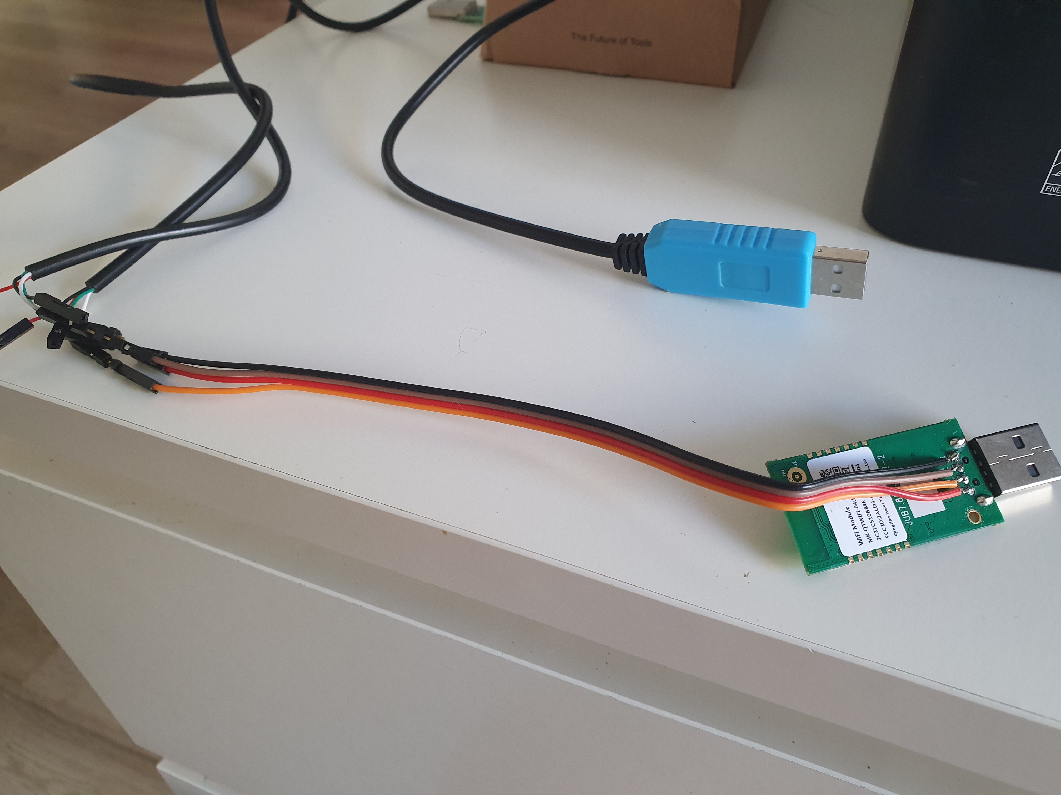
Hi @KoalaBear.
Here is the photo of the WifiModule with the wires soldered.

To be able to know the protocol between the Wifi module <-> Haier unit you can spy this communication soldering those wires on wifi module. Once you’ve got it soldered all you have to do is take 2 ftdi cables (serial <-> usb) and connect the each one of the rx of the cable to the wifi module.
On your laptop then you’ll be able to see the communication between wifi module and the haier unit

I hope it helps.
Let me know if you have any doubt.
1 Like
Finally received the FTDI (click to see pins), just under 2 months 
And in other topic posted the USB extension cable I modified to ‘intercept’ it, hopefully. I kept the same official colors to make it easy 

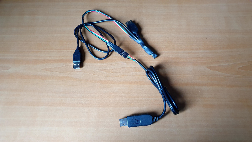
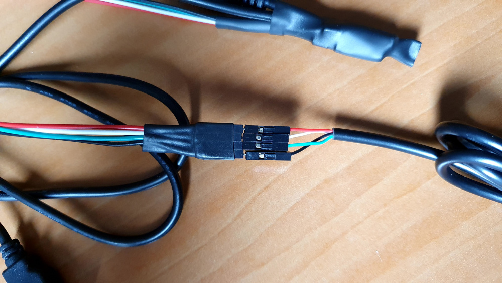
Can you verify that it is correctly connected like this? With the RX/TX etc, or should they also be reversed? Thanks!
Hi!!
The idea is to spy the Wifi module communication with the Haier unit, right?
You should connect your FTDIs cables like in the diagram:
On the diagram the USB connectors are the FTDI cables.
Basically you’ll have to solder cables on the wifi module and connect those cables to your ftdi’s and then you’ll be able to spy the communication with some computer program such as Docklight.
Thanks, will try it later. Found this very funny: https://twitter.com/tomfleet/status/1299714259908202498