I have searched high and low for an answer to this one, so hopefully someone can help educate my n00b brain:
I have a Battery connected to my solar panel array, via charge controller, and I would like to hookup an energy meter to it (PZEM-017) which has support in ESPHome. I understand that the PZEM-017 doesn’t have UART output, so I have also purchased a TTL to RS485 converter and have connected the PZEM-017 to my D1 Mini32 Clone per this diagram:
I use a D1 mini 8266 and a 5V / 3.3V level converter, because the output of the converter rs485 is 5V and the D1 mini to GPIO is only 3.3V.
I don’t understand the Entity is non-numeric?
I use GPIO5 (D1) and GPIO4 (D2)
I’m powering the esp32 with a usb plug, and passing 5v to the rs232 to ttl adapter and the PZEM-017. Should I be sending those devices 3.3v from the esp32 instead?
I am supplying the PZEM-017 5v from the esp32 (in parallel with the RS232 to TTL adapter from the usb pin of the esp32). Do I still need the logic level shifter for the data?
I am connecting the TX to RX and RX to TX appropriately from the esp32 to the RS232 to TTL adapter
If you use nodemcu8266 instead of D1 mini, no level converter is needed because nodemcu is tolerant to 5V on GPIO. This is also written in the manual PZEM.
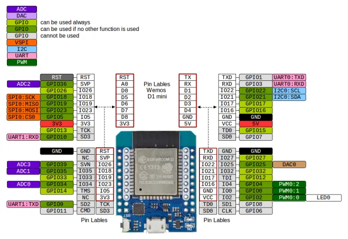
I am using this board, which is effectively a d1 mini32, but the listing also says nodemcu, so it’s confusing. I am using this image as a pinout reference
My information is that the mini boards are only GPIO 3.3V and this is a mini board. I have the same here. Try using GPIO 21, 22 (D1, D2).
There is a danger that you will destroy 5V GPIO. It may not be immediate, but over time it will.
Yes correct. I also have a PZEM-017 and I am measuring the current coming into the battery. The second measurement is the current coming from the battery. I don’t have D1mini32 but only D1mini 8266
What you still have with the RS232 board, you need RS485-TTL
For the board in OP’s picture, you want D1 TX to 485 TX and D1 RX to 485 RX. The boards are labeled weird. Also you probably want a 120 Ohm resistor across A and B. See my post Alpine Boiler with ESPHome Modbus Sucess
Thank you for the tip about the TTL to UART module. If I connected a resistor in parallel to A and B on the converter, instead of down the wire an inch or so, would that solve the issue of reflection, or would that be too close?
As for the TX and RX…are you saying the TTL to UART module is incorrectly labelled? I’m using the Mini ESP32, which is not the D1 Mini in the original picture with the first post.
Mine is only down a couple mm from the terminals on the stripped wire end, but not directly across the terminal. I guess try and see if it helps. It was necessary for me, but I am connecting to a different device than you.
Yes, if you have the TTL 485 board in the picture, it is mislabeled according to the standard convention. The TX goes to the ESP TX and the RX to the ESP RX. Shouldn’t matter what ESP board you have. In this youtube video at the 2:30 mark, a guy explains it. UART To RS-485 Interface / Pro Mini / LoRa Interface - YouTube
An interesting idea with a 120 ohm resistor between the A + B terminals of the converter. Mine works without it well see the measurement entities in the picture.
I should be receiving the level shifter today, but shouldn’t the pzem-017 work with the ttl to uart adapter without it, even if it’s not the right level???