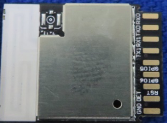
Help trying to flash ESP32 in Home Depot bulb

I bought an RGBWW downlight at Home Depot because the FCC filing showed it used an ESP32 and I hoped to reflash it with ESPHome.

https://fccid.io/2AB2Q-LA02301/Users-Manual/11-User-Manual-4810925
https://compliance.ioxtalliance.org/product/226

I can’t seem to figure out how to get it to accept the new firmware. Is it possible for it to be protected from being reconfigured with other firmware?

1 Like

You probably need to short the IO0 pin to ground when powering up to put the ESP32 in bootloader mode.

You can leave it shorted through the entire flashing process or disconnect it once flashing has begun.

I tried that both with GPIO0 and the pin listed as Factory Mode N, can’t seem to get it to go into boot loader mode. Yes, VCC is set to 3.3, gnd to gnd, tx to rx, rx to tx. I’ve done this process with a son off basic and other 8266 devices, but not with ESP32 or this particular PCB assembly. Figured it’d be simple.

I’m curious- what is the model# or Home Depot SKU?

1 Like

Do you have a picture of the other side of that vertical daughter board?

Try applying 3.3v to the RST pin also GPIO2 should be floating or pulled to ground. GPIO0 to ground.

The SKU is 1005731250

1 Like

There isn’t much on the daughterboard on the other side. The LeedArson assembly, containing the ESP32, is soldered onto the daughterboard and that daughterboard connects to the power and color channels, in addition to exposing the connections you saw on the other side.

On the daughterboard, R is PWM1, which the documentation says is GPIO0. B is GPIO2.

I have tried applying ground to those while plugging in the USB to UART adaptor, still nothing, ESPHome times out when trying to upload.

After digging into one of these Home Depot devices (Defiant HPPA11CWB) with the same chipset, I see a message that seems to indicate that the bootloader has Download Mode disabled :frowning_face:

1 Like

I can confirm the bootloader seems to be disabled. I have the Smart Recessed Kit from Commercial Electric that bought from Home Depot. The module is a LA02301. I ended doing a transplant with a M5Stack Stamp. Still a little too big for the enclosure but I can 3D print one.

I connected the Red to G26, Green to G25, Blue to G18, WW to G19 and CW to G22. I connected “D” to G21 but I couldn’t figure how it works.

{“NAME”:“Afero Recessed”,“GPIO”:[0,0,0,0,0,0,0,0,0,0,0,0,0,0,418,420,0,0,419,0,0,417,416,0,0,0,0,0,0,1,0,0,0,0,0,0],“FLAG”:0,“BASE”:1}

I recently grabbed a couple of the Commercial Electric Smart Dimmer with Motion Sensor devices due to the claim of having BT and WiFi connectivity, with the hope that that entailed having an ESP32 inside.

Sure enough, it appears to be an ESP32 by Afero, Inc., but I’m not aware of what pin is GPIO0 based on the board markings and the back of the ESP32 chip being obscured. This would be SUCH A COOL product if I could get ESPHome on it, as I really like the clean look and the built-in PIR.

Is there any way to force new firmware on the ESP32 or emulate an OTA update that anyone knows of? @parrotmac and @csaleman you both have at least some knowledge it seems of the bootloader being disabled.

If someone can post a picture of the back of that ESP32 chip being used, I’d love to at least figure out which pin is GPIO0 to try entering flash mode for this device!

Pictures of the board in this product (I moved the QR sticker off the heat shield while checking for markings):

20211224_174705|375x500

.

Hi @taylorlightfoot any success on flashing? I have the same board in my smart plug. Wanted to follow your path if you have succeeded.

1 Like

I haven’t tried since last commenting. Issac seems to be onto something as to why it’s not working. Best guess is the OEM have their software encrypted and some sort of protection mode enabled so people can’t read their code. I don’t know enough about this stuff, I’ve only flashed a handful of ESP devices, and most were dev boards bought with that intention. I’ve flashed a Sonoff basic with ESPHome though.

There is no code to read. Just binary that could be decoded into assembler code, but that’s all someone could do.

I suspect that the manufacturer burned an eFuse that write protects progmem.

Just a guess.

So, buy an ESP32 module, flash espHome on it then solder it to the light’s PCB.

I am also working the Commercial Electric Smart Dimmer with Motion Sensor. Good idea on a transplant, might try with a wemos on the next one I pick up. The chip is the same
LA02301 mentioned by the OP.

I almost have the Hubspace API reversed engineered. The company says they are interested in providing an API and were not 100% thrilled that I said I was working on figuring it out. Anyways, as of now, I can go from Username/password all the way to reading device state. I think it could be easily turned off by the developer if they figure out what I am doing… @boilermaker I’ll tag you in to test it once I get it working if you are ok using python command line.

1 Like

Thanks for the mention @jaaem. It sounds like you’ve done some good work on this. I returned the smart motion dimmers after confirming that they weren’t able to be flashed and for now I’m using some Linkind dimmers (4-pack seems unavailable on Amazon, and they don’t have motion obviously). Amusingly, the Linkind dimmers have a circuit board that has nearly the same features for a PIR to be included in the circuitry for future products, it appears.

There are a number of folks over on the digiblur Discord who are eager to get a motion dimmer working locally and were all eager to see if this Commercial Electric product would be usable. I would imagine some of them still have the hardware handy if you want some much more savvy people trying to give some python commands a shot.

No local control, but got on/off integrated into homeassistant via the cloud.

1 Like

Screenshot from 2022-05-16 11-54-56
Screenshot from 2022-05-16 11-55-14
Here are some photos of the pinout of the module. I got them from the FCC website. I hope that helps someone with the dimmer. I am interested in using the dimmer if someone can make it work.

This is a link to the manual for the module, showing a pinout description
https://fccid.io/2AB2Q-LA02301/User-Manual/11-User-Manual-4810925.pdf

As a note if you ground “Factory” pin on boot, then your can use serial pins (factory serial) to talk with the chip. Speed is 460800,8N1.

It would reply with 0xD9 to any input, I guess it is a sync frame of a kind.
“Factory” protocol itself remains a mystery.

Without any input it would output repeating sequence at 1 byte per second.

(hex)
49 64 40 49 D9 D9 D9 64 64 64 49 64 64 49 D9 40 D9 49 49 49 40 64 40 40 64 64 40 40 D9 64 49 49 49