Help with reed switch and esphome

Hello all,

I have found this nice project and tried to implement it. First I went with the exact same equipment as it was described and it worked but then I realised I will have to change batteries at some point so I figured which I didn’t like. Since I have my sprinklers running with a nodemcu esp8266 and two switches I figured I should connect the rain gauge there too.

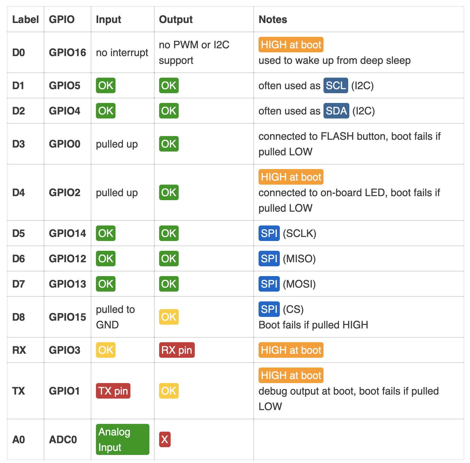
I have connected the two wires from the rain gauge to the esp8266 GND pin and to the D4 but I get no state change in the binary sensor set for the D4 pin. I have tried to connect the gauge between 3V pin and the D4 pin but still nothing.

Can anyone help me figure out where to connect the wires?
I have the following yaml configured for this esp8266 at the moment:

esphome:
  name: sprinklerswest
  platform: ESP8266
  board: nodemcuv2

wifi:
  ssid: "xxxx"
  password: "xxxxx"
  manual_ip:
    static_ip: 192.168.1.13
    gateway: 192.168.1.1
    subnet: 255.255.255.0

  # Enable fallback hotspot (captive portal) in case wifi connection fails
  ap:
    ssid: "xxx"
    password: "xxxxx"

captive_portal:

# Enable logging
logger:

# Enable Home Assistant API
api:
  password: "xxxxx"

ota:
  password: "xxxxx"
  
i2c:
  sda: D2
  scl: D1
  scan: true

binary_sensor:
  - platform: gpio
    pin: 
      number: D0
      inverted: true
    name: "Tool shed door"
    id: tool_shed_door
  - platform: gpio
    pin: 
      number: D6
      mode: INPUT_PULLUP
      inverted: false
    name: "Rain Drops Sensor"
    id: rain_drops
  - platform: gpio
    pin: 
      number: D4
      mode: INPUT_PULLUP
    name: "Rain Gauge"
    id: rain_gauge

sensor:
  - platform: bmp085
    temperature:
      name: "Outside Temperature"
    pressure:
      name: "Outside Pressure"
    update_interval: 60s
  - platform: adc
    id: source_sensor
    pin: A0
    name: ADC
    internal: true
    update_interval: 250ms
  - platform: wifi_signal
    name: "Tool shed WiFi Signal Sensor"
    update_interval: 60s

switch:
  - platform: gpio
    pin: 
      number: D5
    inverted: true
    name: "Valve 1"
    id: valve_1
  - platform: gpio
    pin: 
      number: D7
    inverted: true
    name: "Valve 2"
    id: valve_2
  - platform: restart
    name: "Sprinklers2 restart"
    id: restart_switch_sprinklers2

time:
  - platform: homeassistant
    on_time:
      - seconds: 0
        minutes: 0
        hours: 4
        days_of_week: MON-SUN
        then:
           - switch.toggle: restart_switch_sprinklers2

I have had two downpours here and I registered nothing from this sensor!

Have you tried to use another pin?

This image suggests D4 is always pulled up

I have used D8 but that didn’t work either. Given that I have all the others connected, I am not sure which to use! I could try to use D0 since I have not physically connected anything there. Would that be ok?

Yes you could try that.

You could also still go the aqara/battery way :wink: I have it running now for 1.5 year and did not have to change the battery yet.

i might end up doing that in the end if it doesn’t work! I had an overly ambitious project for it but it seems my skills are still lacking! i’ll try and let you know!

Be careful, D0 and D4 HAVE to be high when the ESP boots up, or it won’t come up. So usually not a good idea to connect a switch to those pins.
You might want to a add another ESP to do this.

but why didn’t D8 work? and am I doing it correctly? one wire to a D pin and one wire to GND or to 3V? Which is correct?

I think if you use D8 you should connect it to 3.3v and use the mode INPUT_PULLDOWN

if I try that it says that only GPIO16 supports INPUT_PULLDOWN. That is D0. I’ll try that.

1 Like

NVM, I screwed up and misread the table above.

Its D3 and D4 that you should not use for switch inputs. D0 is fine.

Randy

Additionally mentioned should be this nice project here:

Same same but different (it doesn’t count the rain but tells you if it rains or not)

Also worth mentioning the esphome category in this forum: ESPHome - Home Assistant Community

yes! I used that project too! I have a rain drop detector too and that works great! I still have some tweaks but it works!

I have tried D0 and it works like this:

  - platform: gpio
    pin: 
      number: D0
      mode: INPUT_PULLDOWN
      inverted: true
    name: "Rain Gauge"
    id: rain_gauge

Why do you say not to use it?

NVM, I screwed up reading the table above.

D3 and D4 are the pins that you should not use for inputs.

Sorry about that.

Randy

so D0 is safe and ok? sweet! now I have to wait for rain again…

Also you are so right! I was reading up on esp32 and boy oh boy it is so nice for not much more! I will change to it as soon as I have the time to solder a breakout board for it!

now I wait…
image

Well the esp32 is very nice, I would not change it a 8266 unless you want to add more stuff the 8266 can not support.
I have a bunch of 8266’s around the house, installed before esp32’s were around, and they are serving their purpose so I am not replacing them.

Randy

Hi @luciandf , I’m about to try the same thing with this gauge and ESP8266. Did you succeed with this project and if so, what did you discover was the working layout?