Oh no, another message starting with “Hello, I’m a newbie”…
But that’s right, I’m a newbie in designing circuits and I’m looking for a straightforward method that could help me figuring out safe solutions for electrical projects requiring parallel and/or series wiring.
Specifically, I’m looking to answer to these questions:
What would work best in a particular project? A parallel or a series circuit? (including current gains and losses of each case)
Which power source (Amps, etc.) cables (AWG, etc.) shall I use?
Possible tips for the wiring (soldering practices, existent quick wiring solutions, etc.)
I thought that this guide could be of great use for the community, hence it’s category. Maybe there’s already something simple I can follow, pardon me, couldn’t find it so far.
So there really isn’t a “best” way as you suggest as it definitely depends on what you are doing. As far as series and parallel, I don’t know what your experience is with electrical but basically.
In a series circuit the resistance of the circuit is increased as the individual resistance of each device is added together since the electrical current is forced to push (current) it’s way through each device. In a parallel circuit, each parallel circuit becomes a new path for the current to split itself between therefore the circuit resistance decreases based on the resistance of each path. (Rtotal=1/(1/Rpath1)+(1/Rpath2)+(1/RpathN)) ohms law is what you are looking for here.
In your second point, again power supply choice is determined by what you are trying to achieve, if you are trying to increase your amps (current) this will completely depend on where you are doing this project and where you can source your power from. Awg (America Wire Guage) would typically be cm (Circular Mills) (measered in millimeters square mm2) for most of the rest of the world. These are measurement numbers for the diameter of the wire that is going to be used to conduct the electricity. Typically a larger wire diameter will pass (conduct) more current. Different wire materials definitely affect this, is it an aluminum wire or a copper wire? As far as soldering, this is definitely a learned skill. I would recommend a soldering iron with an adjustable temperature as you want to be sure that your iron is not too hot but “just hot enough” keep in mind that whatever you are soldering likely is also a good heat conductor and the heat from the iron can and will conduct to other things (melted wire insulation, melted plugs, circuit pads lifting) this will cause frustration. Practice, practice, practice. My personal tip is to heat the location to be soldered before adding the solder. I would also say to use a “rosin” core solder as well, as a small diameter solder to make it more precise.
I trust others will have other input and experience, but that’s mine.
Can I power them in parallel using this power supply? Or shall I go to a series configuration? The motors are not supposed to work all at the same time;
Also, I have one D1 Mini controlling each of the motor. Can I power them using their mini USB to the same power supply? And can I use also parallel and series with them? D1 Minis are supposed to be permanently ON.
Which wire dimensions shall I use?
Ok, I’m aware I’m asking a lot of questions, and probably suggesting very wrong possibilities. Comes with the newbie package, sorry.
Thanks again for any help I can get.
EDIT: I live in a AC220W European country.
It is a very broad topic and I am definitely not going to attempt to answer it all but here is a start. You mentioned you have a 5 volt 3 Amp power supply. In addition to what I mentioned above when you connect a power supply your loads or devices (servo motor controllers) each will require electric power. I have not looked at your part numbers but they will likely have a “power” rating which will include their voltage and current (amps) requirement. I expect the voltage is 5 volts (i did not confirm this), since this is the voltage of your power supply you will need to connect your “loads” in parallel. When you connect loads in parallel each load gets the same voltage but now your overall load resistance drops therefore the current of all your loads are added together, you must make sure that the sum of the load current does not exceed your power supply. Personally I would likely stay below 80%. You cannot just connect your loads in series as the 5 volts will then be split up between each load depending on that loads resistance (ohms law again). If all your loads have the same resistance than in series each of the 4 loads will only get 1/4 of the 5 volts. As far as the wire size goes, you are dealing with pretty small current size so small wire diameter would be sufficient for this.
Here is a sample wire chart to continue your education. https://www.bluesea.com/support/reference/529/Allowable_Amperage_in_Conductors_-_Wire_Sizing_Chart
The current needed for the whole system seems to be suiting the capacity of the power supply, so I can proceed with this right?
If I’m doing it right, I can even double the circuit, with 8 motors and 8 D1 minis, right?
Note 1: I could not find the DC resistance of D1Mini, but I still don’t understand why I need it. Anyway, I assumed 1 Ω for each.
Note 2: D1 Mini is supposed to work at 3.3V, but I’m powering it through the mini USB port, which, according to my readings, allows it’s own circuit to somehow adjusts the 5v to 3.3V.
@tom_l is technically correct on this. I would definitely not think about doubling this circuit. Having the electrical headroom is rarely a bad thing. Another couple things, I am not sure what your project plans are but if your motor are loading up I would suspect the driver circuit would fail before your power supply. Checking the Amazon link you provided I read a comment to add heat sinks to the microchip. This is likely a good idea as when more current is passed through any circuit this usually results in more heat and electronic circuits will fail if they get too hot. Good luck with your design and it would be interesting to hear your results.
Resistance is not to critical for this current is more important. Technically ohms law would say that a current on the d1 mini of 1mA (0.001 Amps) would be 5000 ohms or 5k ohms Resistance. 5 volts / 0.001 Amps = 5000 ohms.
The Wemos D1 typically draws about 75mA. The spec for those motors say they are 200 Ω, and at 5V that would be 25mA each. You could easily power all that with a 3A supply.
The Wemos D1 Mini has a 3V3 regulator that converts the 5V at the USB connector (or the 5V pin) to 3.3V that the processor requires. Note that the GPIO outputs are 3.3V, so make sure your stepper motor driver will work at 3.3V. Do not put 5V on the 3.3V pin.
Thank very much for your help. Learning every hour in this community!
So if they can draw up to five time their rated power I know that I won’t want to have more than two motors working simultaneously.
These are for fertigation purposes, specifically for dosing fertilizers. This means that each motor shall not be working for more than 5 minutes, let’s say, every 24 hours.
Will add heatsinks to the microchip drivers, thank you again for your kind help
Thanks for the hints, it seems you are much better informed than me regarding D1’s. I am using the ones from AZ Delivery, and in their manual they don’t mention these 75mA
For the motors, I read elsewhere that they are 50Ω. So I guess I also need to be careful with misleading Specs.
Regarding the not putting 5V on the 3.3 pin, I got it, from the manual. Now for the other remark you make regarding stepper motor driver working at 3.3, I’m unsure I’m following.
I’m just using the D1-D4 GPIO’s from each D1Mini. I’m powering up the stepper motors directly from the 5V power supply. I didn’t had problems so far. Shall I reconsider my circuit based on this?
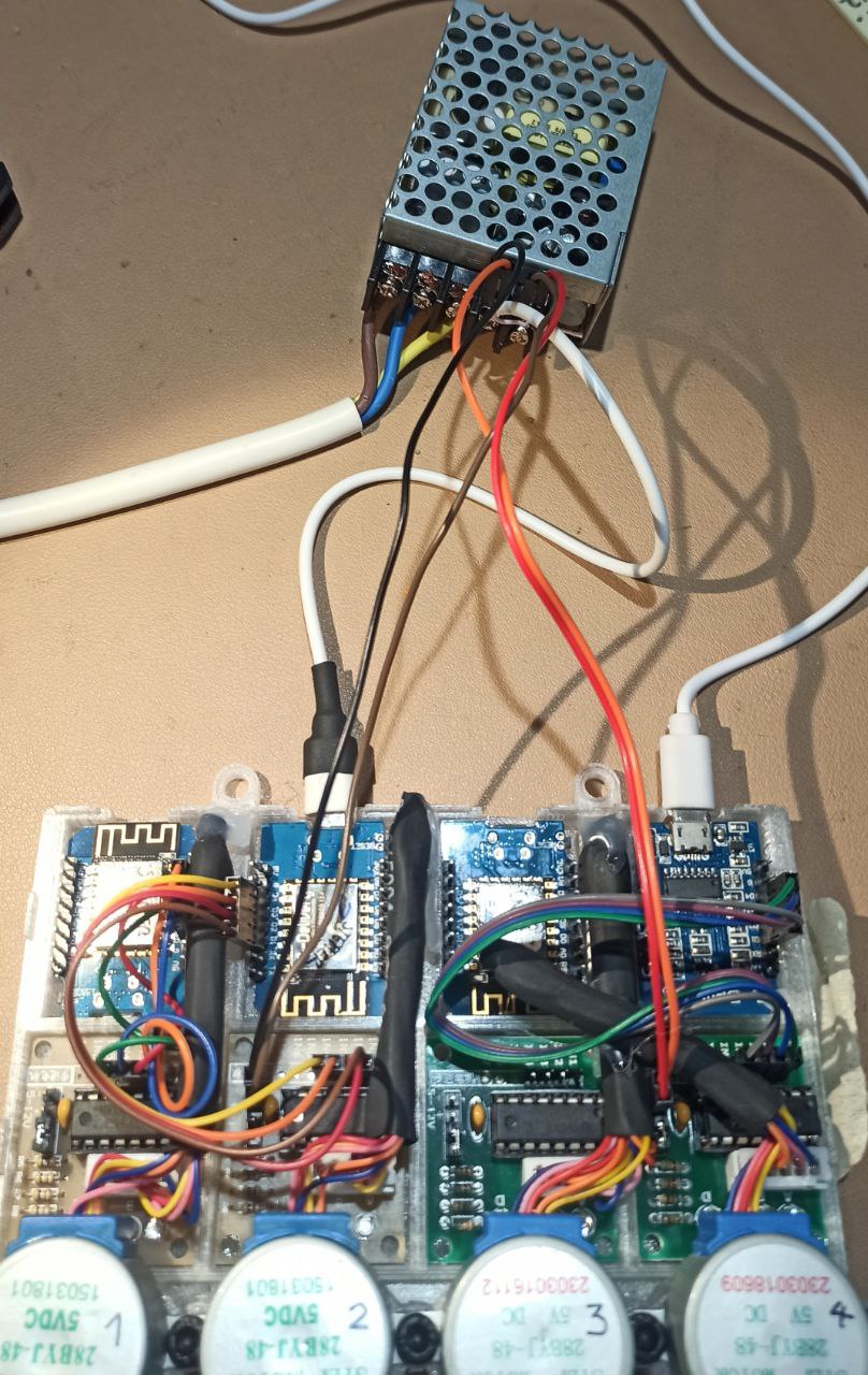
So, this single connection coming out from the power supply (Yellow in this prototype), would take care of all grounds? or should I add more connections from the devices?
(in the example, there are 2 motors completely wired, and one of the D1minis is also powered trough the power supply - in all cases I’m just wiring their “+” and their “-” wire to the respective terminals in the power supply.)
Hello again, so it took me some time because I was figuring out how to re-design the system according to @stevemann@tom_l and @pcwii feedback.
Hopefully you are able to understand the new schematics:
I think I have parallel connections for everything, plus everything is grounded. For the sake of simplicity, please consider everything in double in this schematics (2* ESP32 + 8*ULN2003$motors), except for the power supply, which is now 6.0A, hopefully enough for everything.
Do you think this can work?
Any recommendations for improvements?
Thanks again!
It looks like you got things right. One small item you labeled your input as 220W W stands for “watts” wattage is a measurement of voltage and current (amps) (V * A = W) this should likely be 220 V for volts. Here in North America it would be 120 V (~110 V, ~115 V, ~120 V). Keep us updated on how you make out.