How to power an ESP32 SuperMini board directly from a LiFePO4 battery?

I’m trying to power an ESP32-C6 SuperMini board directly from a single LiFePO4 battery.

I’ve seen so many people online who say they simply connect the battery to the 3v3 pin on the board.

So I did that, but the board is not powering on. With the battery sitting at a comfortable 3.4V, I am reading 2.9V from the output pins of the onboard voltage regulator.

Any advice? Can I simply remove the voltage regulator?

Update: I found the schematic for the ESP32-C3 SuperMini board which is basically the same as mine except the chip, here’s the link: ESP32-C3 SuperMini Board Schematic

I guess you connected it to +5V, correct? That would explain only 2.9V output voltage… You don’t need to remove regulator, connect your cell directly to +3.3V and you’ll be fine.

HOWEVER… when battery will be empty it’s a good idea to have a protection against overdischarge, otherwise you’ll quickly destroy the cell. There are numerous boards for such purpose on aliexpress (that is if your cell doesn’t already have such protection).

1 Like

Thanks @Protoncek No, I connected straight to the 3v3 pin, not the 5v pin. Yet it doesn’t work.

This board is perfectly functional otherwise.

Then it doesn’t go through supermini onboard voltage regulator, which invalidates this:

3.3v pin connects directly to esp32 VDD, so what are these “output pins” you measured?

2 Likes

Some of the 5 output pins of the voltage regulator were at 2.9V and others at 0V, so I assume those were the output pins.

Anyways, I messed up that ESP32-C6 board in the process of trying to remove the LDO. First time using a hot air gun, lessons learned.

Luckily, I have another, extremely similar ESP32-H2 SuperMini board:

So I hooked up the battery at 3.3V to the board’s 3v3 pin, but the board still didn’t power on. I checked the voltages:

  • At the leads of the LDO: 3.3V
  • At the TX/RX pins: 3.3V
  • At the power supply pins (VDD3P3 pins) of the chip (the QFN package): 3.3V
  • At the CHIP_EN pin of the chip: 3.3V

To make sure I didn’t mess up the board somehow, I loaded up an ESPHome script and the board is perfectly working.

Here’s the schematic of my exact board:

Hopefully somebody good at electronics can chime in, otherwise at this point I might give up the dream of Thread-powered ESPHome devices with year-long battery life.

What are these pins ? Where you have them??
If you connect 3.4V lifepo4 battery + terminal to esp 3.3V pin and - terminal to esp GND pin, your esp gets powered and voltage regulator doesn’t have any role here. You don’t need to remove anything from the board.

Obviously you can’t use other power sources simultaneously!

I removed the LDO to avoid backfeed through it, thinking maybe that would help.

This is the LDO on my current ESP32-H2 board, it’s marked LLVB, it tracks to this datasheet.

Show image

Your board has specific pins for battery at the bottom of pcb, on the opposite of usb connector (labeled B+ and B-). Did you connect battery there? You should.
Also - did you really remove ldo, or did you remove battery charger chip? In any case, there’s no need for this. Ldo doesn’t backflow and whole board is made for battery operation without messing with it…

Finally… (but you figured it out that part already): on such small board components like ldo is removed with soldering iron, not with hot air. Hot air is only for big pin number components.

2 Likes

Ok, I see only one output pin, not 5. And where are you avoiding to backfeed? I repeat, you can use the 3v3 pin to power the board, but only when you don’t have other power sources.

1 Like

On this board, as i said, there’s no need as it does have battery power option.

1 Like

For li-ion or lipo perhaps

1 Like

True, but in this case it doesn’t matter, since he won’t have usb connected (hekll run only on battery, as he said), so battery won’t be charged.
But, regardless, connecting to 3.3V pin must work, i see no reason why not, unless some connection was broken with removing LDO… i have a few esp’s running with power connected to 3.3V pin just fine.

EDIT: i looked to schematic again: battery is connected (via diode) to Vbus, which is 5V, so connecting 3.4V battery to that won’t work. So, original idea to connect it to 3.3V is the way to go.

1 Like

but 3.4v through the regulator is likely too low to get regulated 3.3v out…

2 Likes

Yeah, i spoke too soon, i explained above in my edit…

2 Likes

To clarify, this H2 board is untouched, I didn’t remove the LDO on it. That was the previous near-identical C6 board which died while trying to remove LDO.

@Karosm, that’s the thing, I have no other power sources, I’m using the 3v3 pin yet the board is not powering on.

@Protoncek Thanks for the tip on hot air. The board does have the battery pins on the back, yes, but the charger IC is TP4054 and that’s for Li-ion batteries which go up to 4.2V when fully charged. Because of this I assume the output of the battery goes through a voltage regulator/converter before feeding the chip (I can’t find that part in the schematic though…?). I want to explicitly avoid any LDOs for maximum battery life.

If you search online for this ESP32 LiFePO4 setup, people mention connecting directly to the 3.3V pin, not to the battery pins.

Since I’m out of options at this point, I’ll try connecting to the battery pins next (tomorrow).

Check that your battery is fully charged and that your wiring is correct.
Only thing that comes to my mind, that could prevent powering through 3v3 pin would be diode between 3v3 pin and esp VDD. But schematic doesn’t present any…
Post a photo of your battery-esp-wiring

1 Like

Yeah, as i said above i spoke too soon for 3.4V cell…
Output of the charger chip is labelled BAT. It took a while for me to find where it goes, too. See top middle part of schematic, where BAT goes to the diode and to Vcc, which is 5V (input part of VDO).

Regarding “dead board”: perhaps i know what you’re experiencing, but sadly i can’t help you if that’s the case. It does happen to me sometimes, too with esp32 chips: when i program it it won’t boot (but it reboots indefinitely). Then i fiddle with different loaders etc…and once it comes alive. I still didn’t find the cause of it, but it must be something with bootloader address or partition system, i guess.
Try to connect a terminal to uart (rx, tx) and see if you’ll see constant error and reboot messages.
Try to program the board with esphome web loader by installing default yaml (“prepare for first use”) and see if it will start.

1 Like

If you power your (working one) board from usb, what’s the exact voltage measured with multimeter from 3.3V pin?

What is the tiny (open) jumper-pad on the backside of your board? I don’t see it on schematics…

1 Like

It’s late at night.

I decide to give a last try to this absolutely frustrating piece of a board. Why, why does everybody say just connect the battery to the 3v3 pin and it should work, yet mine does not? Two boards in a row?

Surely I must be doing something wrong.

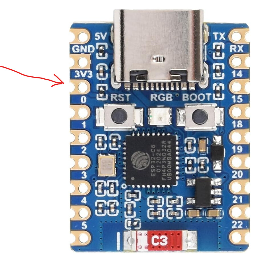
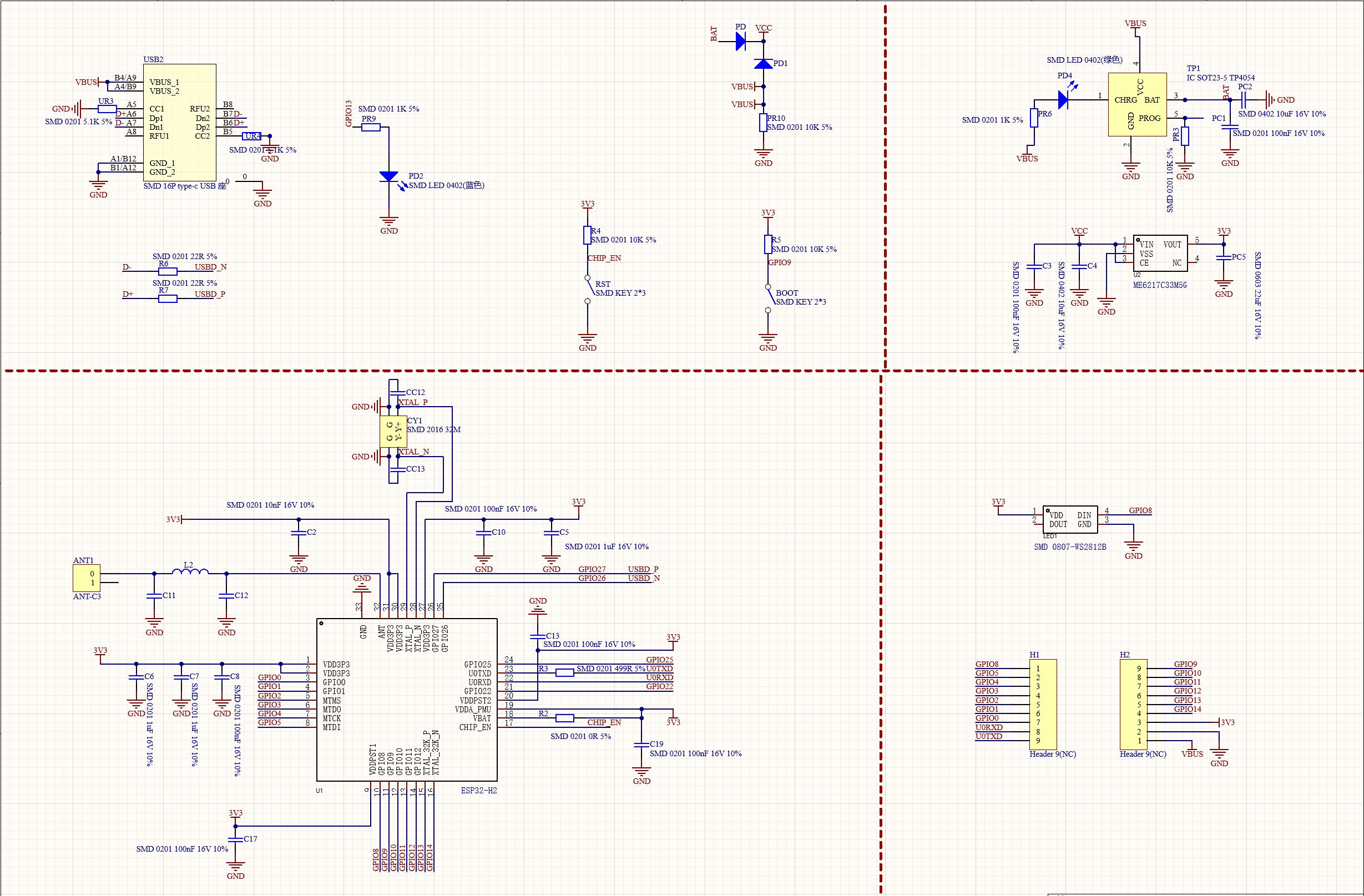
I go over the entire schematic once again, tracing VCC’s and VOUT’s, resistors and diodes, to see what it is that I’m missing.

Nothing. There’s nothing. The 3v3 pin connects to every point that needs power.

I decide to see for myself once again. I take my multimeter, and start painstakingly measuring every last pin, my hands shaking, focusing hard to avoid shorting anything with the needles. GPIO 9 is high, TX/RX are high, CHIP_EN is high, all 4 voltage supply pins of the ESP32 are all high.

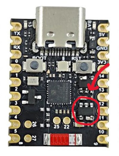
A thought pops into my head. Maybe, just maybe, the board is alive, but only the power LED is not turning on for some reason?

The board was flashed with a simple ESPHome script before. I open ESPHome Builder. The device is shown as online. But, that must be the frequent bug where ESPHome mistakenly shows a device as online, right?

I open Logs. The board was flashed to connect over Thread, over my $5 OpenThread Border Router dongle.

The logs start streaming. I stare in shock. I check that the board shows no signs of life, the power LED is off as usual. I look back at the log monitor. The temp sensor logs 30° once again.

Did I finally become schizophrenic from the stimulants?

No, no, it’s the board that is lying! It’s the traitorous, the corrupt and corrupting, the vile and evil board that is lying!

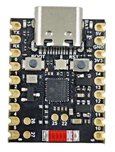
So it was working all along… It was working when I tried to work with the ESP32-C6 board, the H2’s more capable and more worthy cousin, who was disfigured to death by a smoking hot air gun in an attempt to remove its voltage regulator! It was working when I shorted one LiFePO4 cell until it melted its case, in an attempt to revive the dead! And it was working when I shorted another cell and burnt my hand!

All along it was alive and well - yet it was playing dead.

Do not trust these treacherous gobs of sand, dear reader, for they will lie and break your heart.


Huge thanks @Karosm, @Protoncek, I learned a lot trying to troubleshoot this one.

1 Like