I was thinking about adding their MOD-IO2 board in order to use the relays and additional GPIO pins. The relays are for getting my standard doorbell to be “smart” with Home Assistant, based on Frenck’s project here.
However, I have no idea how to do that on the programming side with ESPHome. How do I get ESPHome to recognize the expansion board? What are names for the pins and relays?
The Olimex docs talk about how the boards are “addressable” so they are stackable. But I’m guessing this is not a “plug and play”. Starting on pg. 8 of their documents they talk about various commands for controlling the board, but that isn’t anything like what I’ve used with YAML and doing stuff in Home Assistant and ESPHome.
Any ideas on how to get this to work? I don’t know any programming languages, so this just might be beyond me at this point, as I usually complete projects from tutorials.
Well sorry to be rude but I would say: RTFM Schematics is published by manufacturer: https://www.olimex.com/Products/Modules/IO/MOD-IO2/resources/MOD-IO2-Rev-B-schematic.pdf it’ll give you GPIOs used and so you can then do your sketch for ESPHome easily
The expansion board plugs straight on the UEXT connector your have on the ESP PoE board Just be careful with power supply as I’m not sure PoE is enought to power the relay board properly…
Ha! Thanks for replying. Trust me, I’m well aware I’m out of my zone of understanding here.
I did look at that schematic prior to posting here, but I’m not sure how to find the information I need on it. I’m more than willing to learn, but that schematic is Greek to me. So my fundamental problem is I can’t read the schematic.
For example, the screenshot below is what I suspect is what I’m looking for. But how does ESPHome know to use the GPIO1 on the MOD-IO2 board instead of GPIO1 on the main board? For example, let’s say I have a simple door sensor via magnetic reed switch hooked up to it…how does this differentiate between the main board and the expansion, if both pins are GPIO1? Or in the coding would I call it GPIO0_ICSPDAT? But if that’s true, what about GPIO3? Or maybe those pins aren’t available on the main board, but then that negates the purpose of the expansion board, apart from the relays.
binary_sensor:
  - platform: gpio
    pin: GPIO1
    name: "Test Door Sensor"
    device_class: door
Regarding the power supply, they say in the manual that you need a separate 12V power supply via a barrel connector. Unfortunately they only link to a European version, so that’s another thing to figure out.
One basic thing is you can’t “share” a GPIO (out of specific cases like usirg communication buses: I2C, 1-Wire…). As stated in ESP PoE module you can’t use on the board the GPIO also avalaible on the UEXT connector if you plug something on the UEXT connector ! In your case all GPIO affected at UEXT for your expansion board you have to cosider them as unavaible for anything else
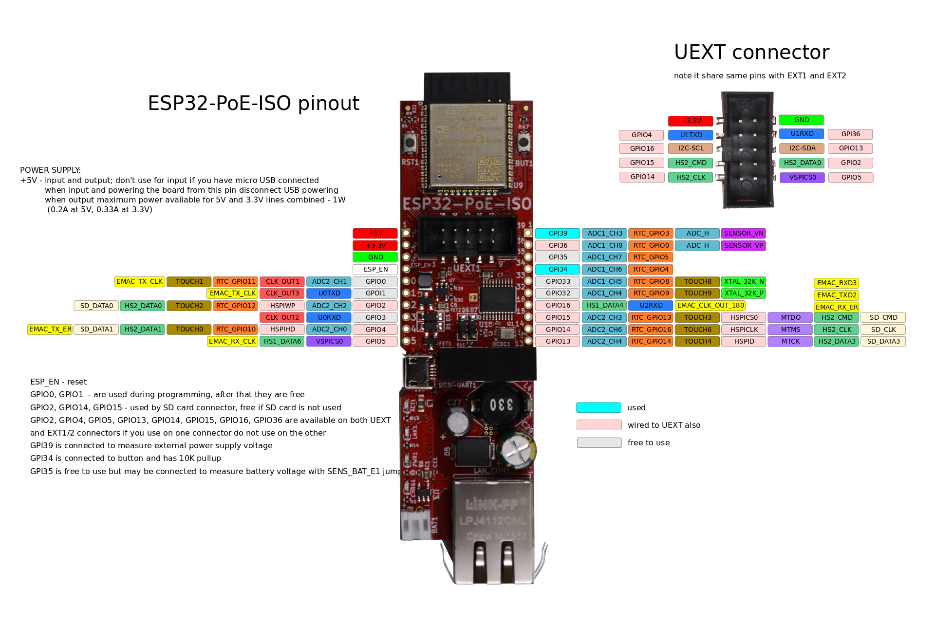
If you want to use some GPIOs on the ESP board you’ll have to be careful they are not already used for the UEXT connector !
Clearly indicated in manufacturer documentation (GPIOs avalaible and ones that are also wired at UEXT connector):
Huh, so I must have misunderstood the purpose of the expansion board. Why would “stacking” them be useful if they don’t give you any extra GPIO pins? What are you “expanding?” Maybe just moving the physical connections off the board?
Hi Ungluedchalice, I have the same setup with the Olimex ESP32-POE and MOD-IO. I have a simulair setup working for mcp23017 GPIO extender via I2c, what works great. No I try to figure out how to program the MOD-IO or MOD-IO2 but cant find any example and get stuck here. The ESP-POE and I2C is working over the UEXT connector but how can I send commands to the board. It looks that the MOD-IO is not a platform. Have you finally get the setup working. If so do you what to share this.
 Schematics is published by manufacturer:
 Just be careful with power supply as I’m not sure PoE is enought to power the relay board properly…

