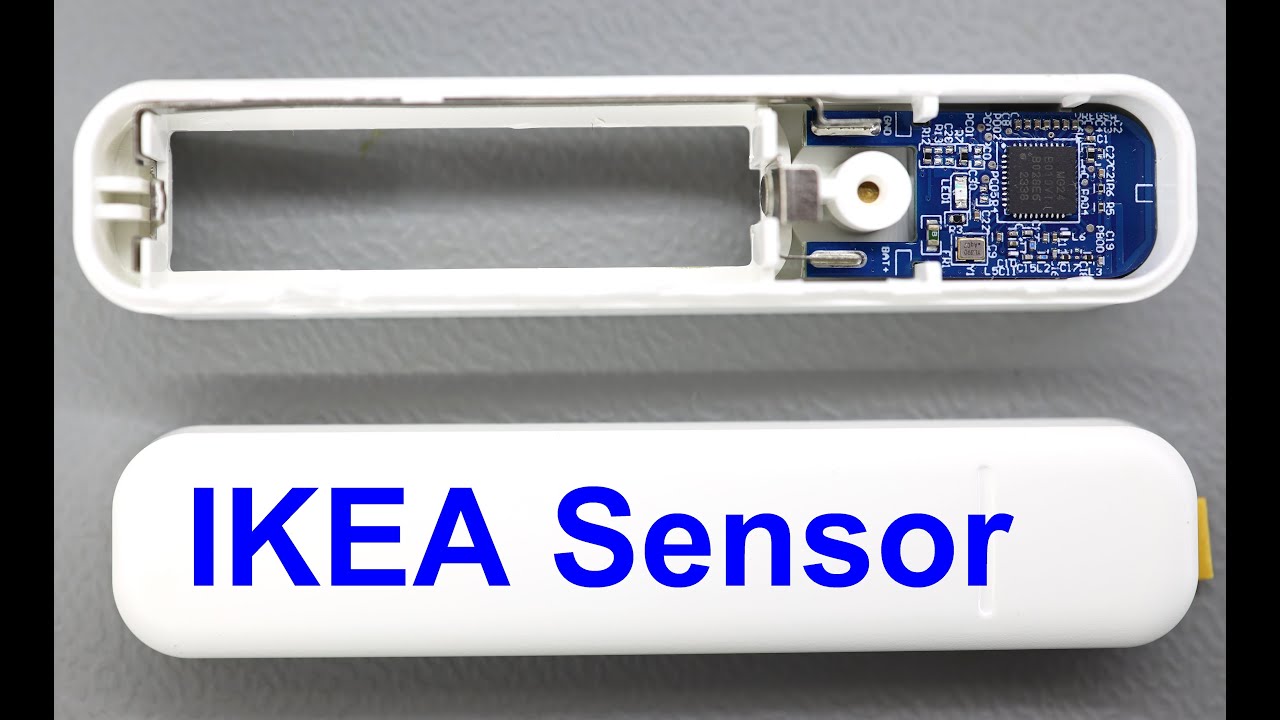
I've seen a destructive tear down before on these new Matter door sensor devices but no info on modifying them. I want to use a remote switch - micro/reed/whatever contact given how cheap these units are they're ideal but the sensor is too big to mount where I need it so here's a rough guide on adding wiring.
First, getting the sensor apart does damage the casing, no way to avoid it, though if you're careful it will go back together maybe with some tape or glue. You want to protect the battery compartment to so it mounts nicely as originally to make life easier in the future.
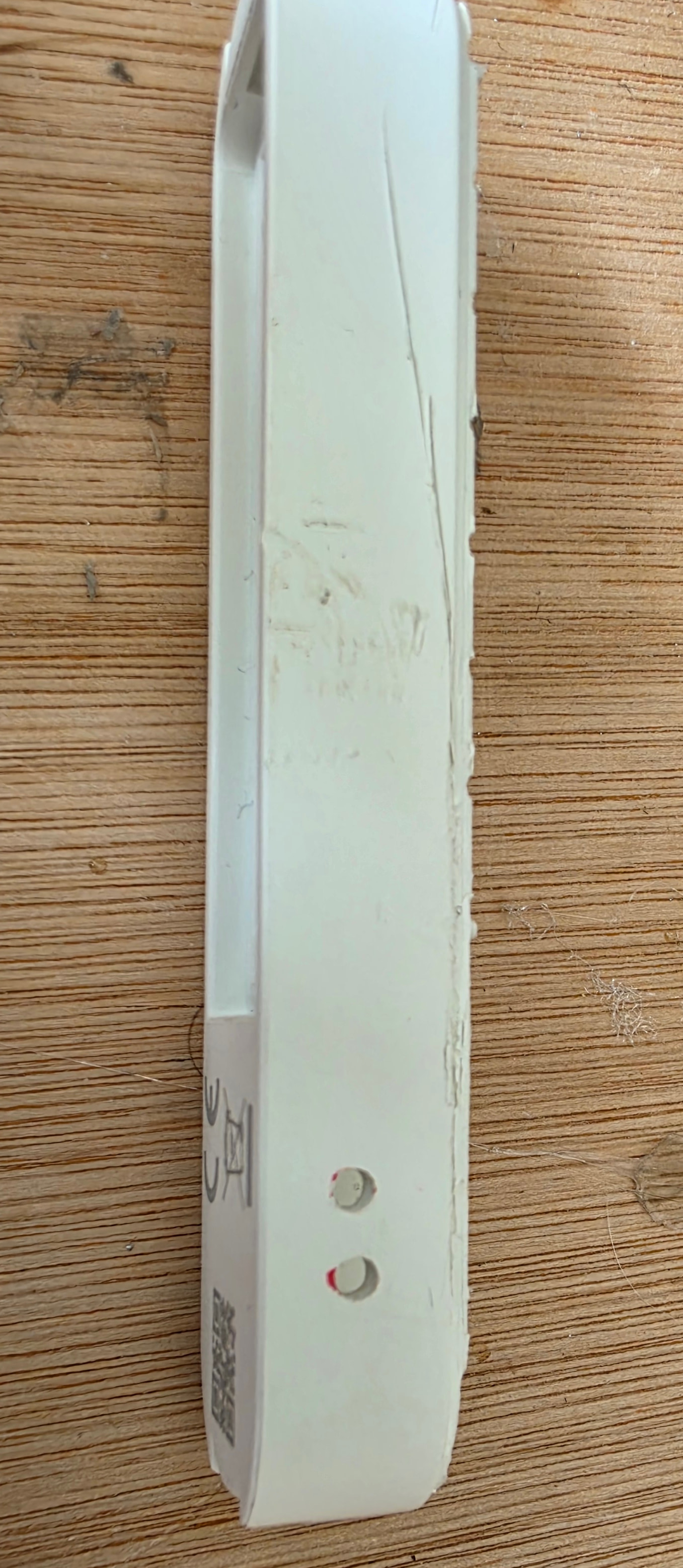
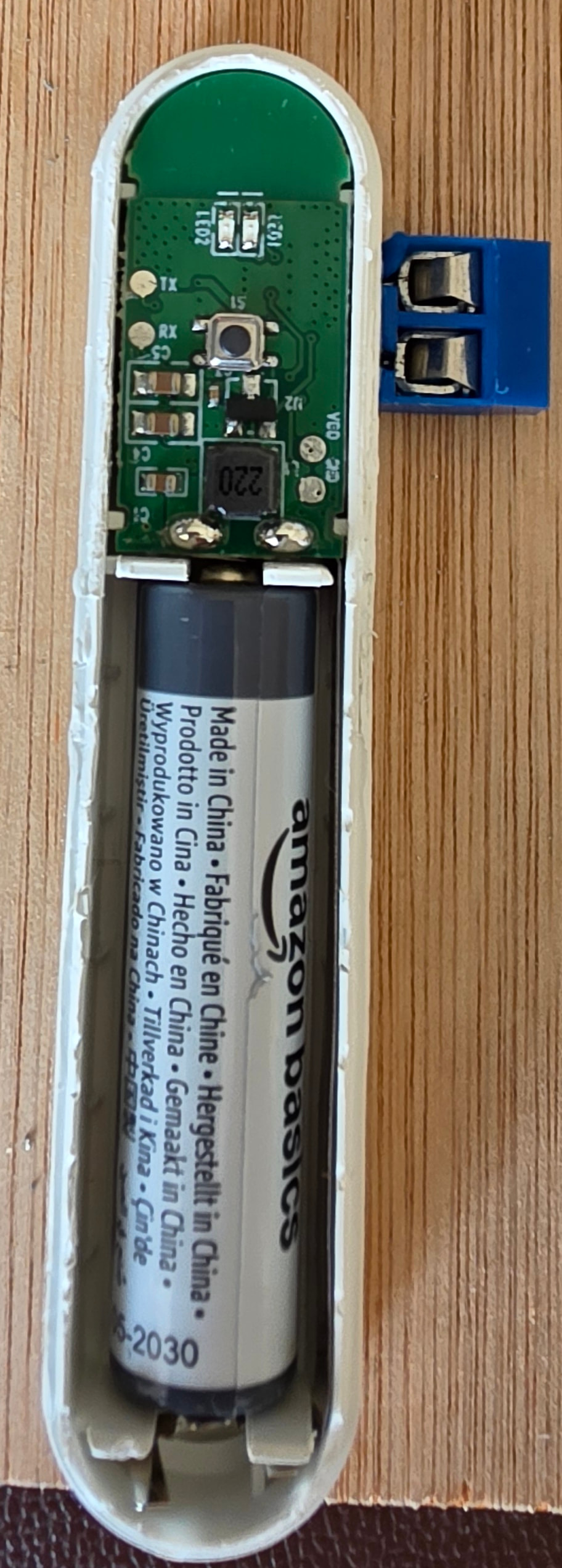
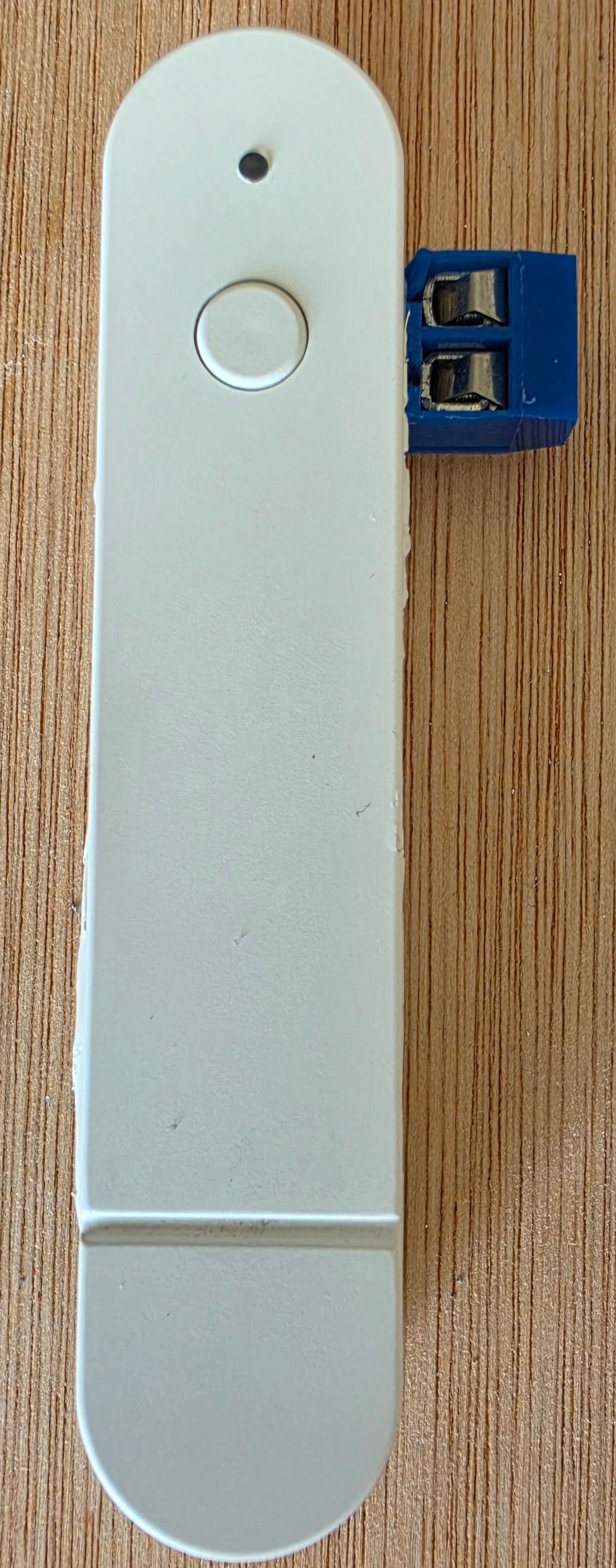
Take the back off, battery cover off and remove the battery. Take a pair of pliers and squeeze the battery compartment around the middle and you'll see the lip of the top cover. Get your spudgers in and carefully unclip it. The following images show what the case looks like, you'll also see it's mostly intact
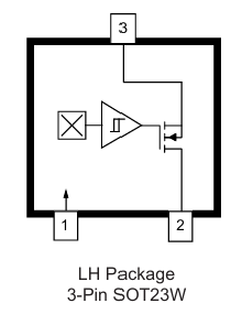
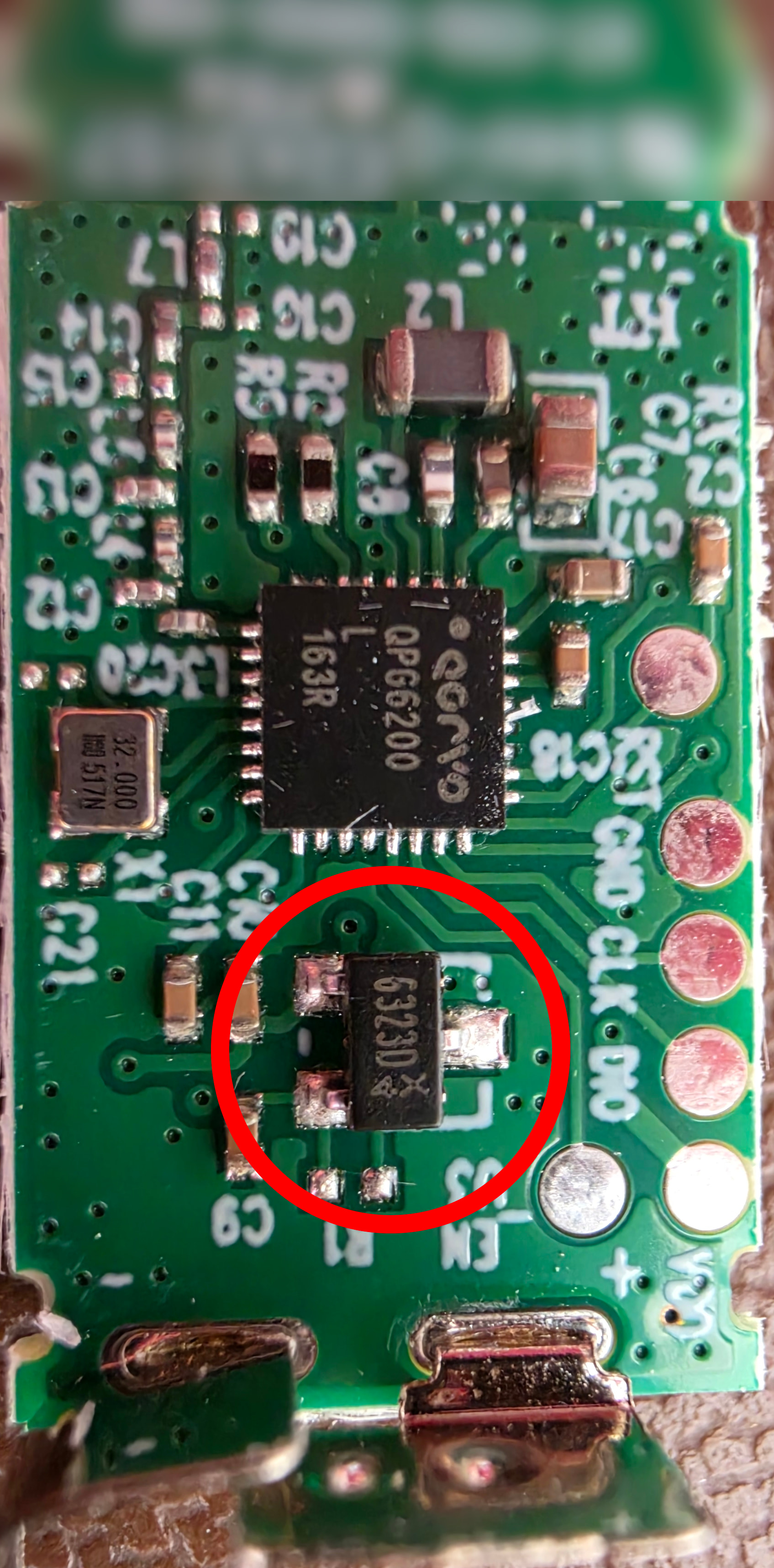
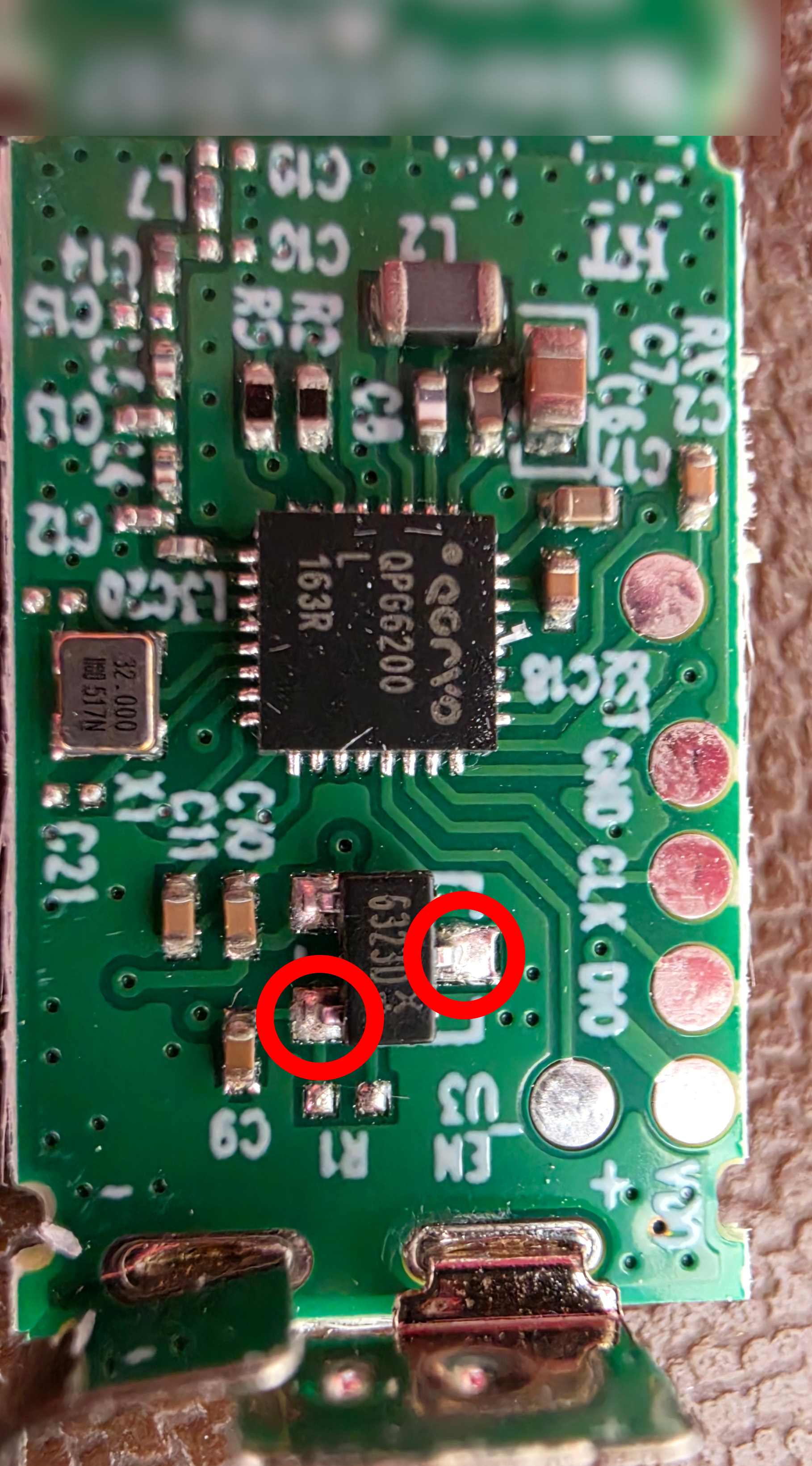
Onto the modifying..... The Myggbett uses a surface mount 6323D Hall Sensor in an LH Package, the schematic looks like this, and we're interested in Pins 2 (OUT) and Pin 3 (GND):
Carefully solder wires to each of the two pins, re-assemble and notch the case for the wiring to exit the casing and wire up to whatever type of switch you want to use. You could de-solder the hall sensor but not sure it's necessary given the magnet will be out of range configured this way. That's it!
Awesome job, really nice guide! I’ve Done the same modification, it works fine until the circuit have been closed for like 8 hours, then the battery is going drained. Have you notised this as well?
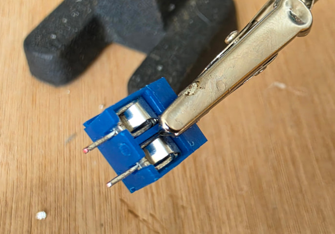
You can use any switching device, reed, micro or whatever you need to trigger the sensor rather than the rather large magnet that it comes with. It’s why I modded in the first place as I can’t fit the sensor or magnet where I want to use it but it can be placed nearby
@mrrafik@wimpie007 Interesting, I’ll do some tests on mine. When the reed is closed, do you see any activity in HA? Is it continuously reporting or anything like that?
I’m wondering if certain mechanisms are causing continual current draw by the hall sensor, it might need disconnecting afterall.
i use a reed switch placed in my watermeter (hole of 4 mm IN the water meter). every 0.5 liter, reed switch is open for a moment. rest of the time it is closed. (internally, some kind of magnetic disc spinning around every 0.5 liter)
So i need to bring the reed switch outside.
the current between GND and OUT draws the battery fast.
Putting a resistor between it wasnt a great succes, the resister needed to be to quit small to trigger on/off.
I even removed the hall sensor completely (destroyed it along the way ), but that didnt work either: without the hall sensor, you can trigger ‘çlose’ by shorting GND-OUT, but it never gets open again.
Im stuck right now.
Is that a serious question? As I said it means you can use a remote switch of whatever type you like mounted in a way that works for the application rather than trying to fit these units which are really quite big.
kinda same thing… on/off is not as simple as providing voltage or not…
firmware is update the latest.
the 3 connections on the hall sensor are just not made to connect regular switches.
Considering the behavior and high battery draw, I would expect that the hall is not just common Open-collector but could be some CMOS type, latch or push-pull, analog or whatever.
QPG6200L is quite sophisticated MCU, with programmable gpios and even comparator onboard. Datasheet gives for example:
“Low Power Comparator event - The low power analog comparator can be configured to wake up the system on a compare valid event.”
Someone with still working hall, could try to probe the output voltages on both stages.
Interesting question remains, why OP doesn’t experience this battery draw problem? Is sensor/circuit different from others?



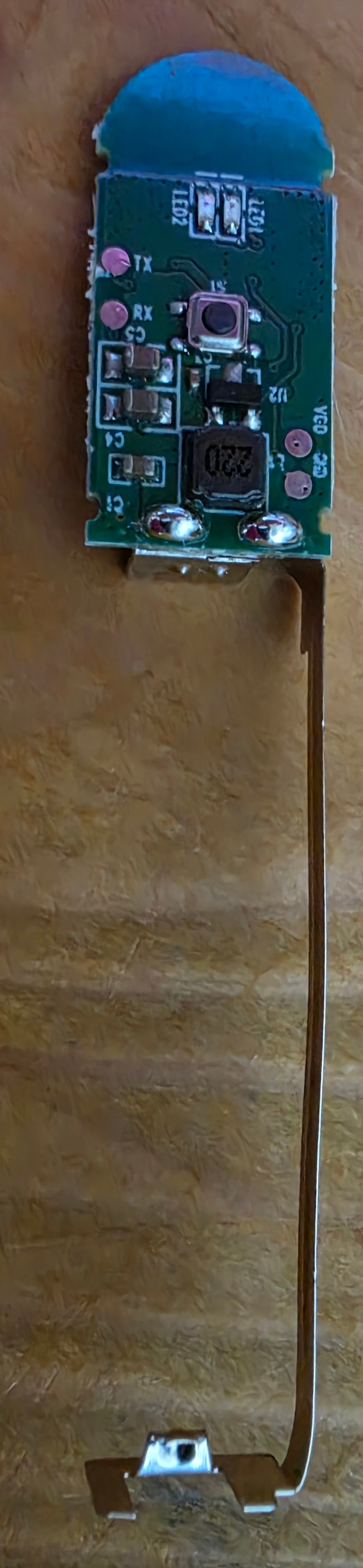
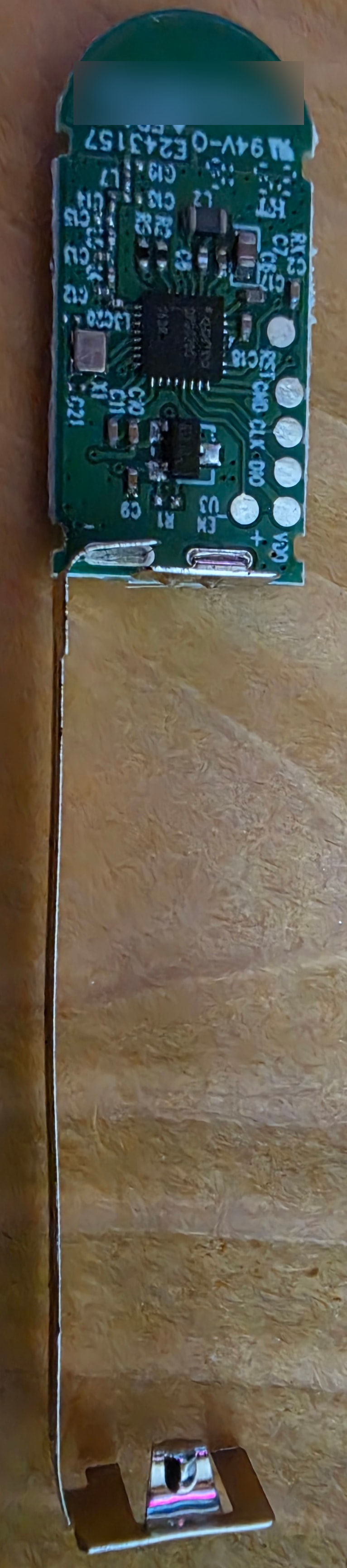


 ), but that didnt work either: without the hall sensor, you can trigger ‘çlose’ by shorting GND-OUT, but it never gets open again.