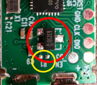
@Karosm Those pictures are from my sensor and the type is shown in the original post it’s a 6323D/SOT23W hall sensor, there’s lots of spec documents to check. You can zoom the pics and check if the part is the same as yours.
I can scope the hall sensor tomorrow if I get chance. I wonder if a diode is required between GND and Signal?
@wimpie007 that “old” zigbee type appears to use a different hall sensor, can’t quite make out what it is from the video but I can see it has a different number on the top of the case.
Hall from most known manufacturer, but do you have some evidence yours could be that (or even similar)?
I tried to find datasheet with those markings on your photo, but it was dead end.
@Karosm No but the google results have been corrupted, partially my fault but I was getting direct matches for the markings on the sensor casing when I first started this process.
I’ve managed to get rapid, visible drain on mine so trying a couple of things. I’ve stopped the drain using a diode but I suspect when the sensor goes to sleep it won’t wake or wake reliably but will leave it over night to confirm before trying the next thing.
That MCU is so sophisticated that I’m not able to guess how circuit works without datasheet of the sensor.
Sensor output voltage probing without additional circuits/components could give some hints though.
Ok having done a bit of testing and tinkering I think there is a solution.
Testing the sensor reveals a VCC of 2.194v so there’s a power circuit in there to take the battery voltage high enough for the switching High/Low state needed by the MCU.
If you remove the output pin on the hall sensor and connect the wire direct to the PCB that should allow the switching to occur without the current drain. However, I wasn’t able to test this as I accidentally removed the whole hall sensor from the board
With the sensor removed it still works, however the state will only switch once, so if you power up with the switch open it will change to closed once and then it will not change again until the battery is removed and replaced again.
To resolve this a pull up resistor is required this needs to go from the VCC pin (the one NOT circled red in my original pictures) to the output pin (Pin 2 right hand side of the sensor as shown in the images VCC top left, GND bottom left, OUT middle right).
a 1M Ohm resistor should mean stand by power usage is about the same as the original.
I’ve not been able to test this properly either as the PCB pad has come off for my VCC pin so will need to track down another place to grab the correct voltage.
So according to your info, that hall could be simply push-pull type.
Unoccupied R1 pads are probably for optional pullup (test before connect).
Edit: If hall without magnet pushes line high and at the same time your diy circuit pulls it down, battery drain is guaranteed. In theory could damage the device as well.
So the working solution would be removal of hall from pcb and adding high value pullup in place of that.
One must try how high pullup resistor reliably still works, megaohm range would be obviously best for battery drain.
Absolutely, I plan on testing it out but ran out of time today to check if the test pads carry V+, I assume they do. Possibly a job for tomorrow. Will update when there’s something new to add.
Ok so had a bit of time today to test the pull up. The test pad + provides the correct voltage. It wasn’t successful though. I used a 10K resistor to remove any doubt about value (obviously using this for real will kill the battery fast) but it will still only trip once, which suggests that the test pad may be managed. Not had change to check the two points in the image above.
I have more things to test but not sure when I’ll get around to it.
??? It means that the test pad provides the correct voltage so my missing pad isn’t an issue and it’s easier to solder to as they’re bigger but with the pull up resistor it still doesn’t allow status triggering more than once, as I wrote above.
First of all I don’t have this device on my hands.
Joining just because I got curious about the symptoms on modified circuits.
I have not clear idea what parts of your board are still functional and what voltages were verified on original circuit.
Is “test pad +” verified to be same as hall vcc?
If there’s no virgin circuit to be probed, only viable approach is logical. How certain partially unknown circuit could be, if output is what you get.