Yes, the microswitch is supported but there are no known configurable properties. It
that surprises me because there is configuration for the micro module in the insteon app (when it worked). there is a config to change the micro module to support single momentary, dual momentary, and latching. so there should be properties. let me know what i could do to help debug.

1 Like
Logging should look like this to see the details of what is happening in Insteon:
Awesome… Thanks!
per previous post no properties/parameters show for micro module 2443-222. According to manual and what I remember from the insteon app, the micro module should have pretty same properties / parameters as the 2477S switch as well as switch operation mode (latching, single momentary, dual momentary). Any idea why they don’t show? Could this be the underlying pyinsteon implementation? Any suggestions to debug?
i did some debugging using the debug settings earlier in this thread. when “load from device” from a 2477s switch, I see a flury of messages in the log. But when I do the same for the micro module, the only message I see in the log is:
DEBUG (MainThread) [pyinsteon.managers.saved_devices_manager] Writing 16 devices to save file
which leads me to believe that clicking “load from device” in the insteon control panel for the micro module does not send any messages to the device. why would no message be sent to query the module? The micro module 2443-222 clearly has properties
When doing the same with 2477S I get:
2022-05-09 20:12:54 DEBUG (MainThread) [pyinsteon.topics] Topic: send.get_operating_flags.direct data: {‘address’: 384649, ‘flags_requested’: 0, ‘extended’: False}
2022-05-09 20:12:54 DEBUG (MainThread) [pyinsteon.messages] TX: msg_id: 0x62, address: 384649, flags: 0x00, cmd1: 0x1f, cmd2: 0x00
2022-05-09 20:12:54 DEBUG (MainThread) [pyinsteon.protocol.messages.inbound] IN CREATE: 0262384649001f0006
2022-05-09 20:12:54 DEBUG (MainThread) [pyinsteon.protocol.messages.inbound] Returning:
2022-05-09 20:12:54 DEBUG (MainThread) [pyinsteon.messages] RX: msg_id: 0x62, address: 384649, flags: 0x00, cmd1: 0x1f, cmd2: 0x00, ack: 0x06
2022-05-09 20:12:54 DEBUG (MainThread) [pyinsteon.topics] Topic: ack.384649.get_operating_flags.direct data: {‘cmd1’: 31, ‘cmd2’: 0, ‘user_data’: None}
2022-05-09 20:12:54 DEBUG (MainThread) [pyinsteon.protocol.messages.inbound] IN CREATE: 025038464925ef3b201f00
2022-05-09 20:12:54 DEBUG (MainThread) [pyinsteon.messages] RX: msg_id: 0x50, address: 384649, target: 25ef3b, flags: 0x20, cmd1: 0x1f, cmd2: 0x00
2022-05-09 20:12:54 DEBUG (MainThread) [pyinsteon.topics] Topic: 384649.get_operating_flags.direct_ack data: {‘cmd1’: 31, ‘cmd2’: 0, ‘target’: 25ef3b, ‘user_data’: None, ‘hops_left’: 0}
2022-05-09 20:12:54 DEBUG (MainThread) [pyinsteon.topics] Topic: handler.384649.get_operating_flags.direct data: {‘group’: 0, ‘flags’: 0, ‘response’: 0}
2022-05-09 20:12:54 DEBUG (MainThread) [pyinsteon.managers.get_set_op_flag_manager] Received set command response: 0
2022-05-09 20:12:54 DEBUG (MainThread) [pyinsteon.topics] Topic: send.get_operating_flags.direct data: {‘address’: 384649, ‘flags_requested’: 5, ‘extended’: False}
2022-05-09 20:12:55 DEBUG (MainThread) [pyinsteon.messages] TX: msg_id: 0x62, address: 384649, flags: 0x00, cmd1: 0x1f, cmd2: 0x05
2022-05-09 20:12:55 DEBUG (MainThread) [pyinsteon.protocol.messages.inbound] IN CREATE: 0262384649001f0506
2022-05-09 20:12:55 DEBUG (MainThread) [pyinsteon.protocol.messages.inbound] Returning:
2022-05-09 20:12:55 DEBUG (MainThread) [pyinsteon.messages] RX: msg_id: 0x62, address: 384649, flags: 0x00, cmd1: 0x1f, cmd2: 0x05, ack: 0x06
2022-05-09 20:12:55 DEBUG (MainThread) [pyinsteon.topics] Topic: ack.384649.get_operating_flags.direct data: {‘cmd1’: 31, ‘cmd2’: 5, ‘user_data’: None}
2022-05-09 20:12:55 DEBUG (MainThread) [pyinsteon.protocol.messages.inbound] IN CREATE: 025038464925ef3b201f0d
2022-05-09 20:12:55 DEBUG (MainThread) [pyinsteon.messages] RX: msg_id: 0x50, address: 384649, target: 25ef3b, flags: 0x20, cmd1: 0x1f, cmd2: 0x0d
2022-05-09 20:12:55 DEBUG (MainThread) [pyinsteon.topics] Topic: 384649.get_operating_flags.direct_ack data: {‘cmd1’: 31, ‘cmd2’: 13, ‘target’: 25ef3b, ‘user_data’: None, ‘hops_left’: 0}
2022-05-09 20:12:55 DEBUG (MainThread) [pyinsteon.topics] Topic: handler.384649.get_operating_flags.direct data: {‘group’: 5, ‘flags’: 13, ‘response’: 0}
2022-05-09 20:12:55 DEBUG (MainThread) [pyinsteon.managers.get_set_op_flag_manager] Received set command response: 0
2022-05-09 20:12:55 DEBUG (MainThread) [pyinsteon.topics] Topic: send.extended_get_set.direct data: {‘address’: 384649, ‘data1’: 1, ‘data2’: 0}
2022-05-09 20:12:56 DEBUG (MainThread) [pyinsteon.messages] TX: msg_id: 0x62, address: 384649, flags: 0x10, cmd1: 0x2e, cmd2: 0x00, user_data: 01.00.00.00.00.00.00.00.00.00.00.00.00.d1
2022-05-09 20:12:56 DEBUG (MainThread) [pyinsteon.protocol.messages.inbound] IN CREATE: 0262384649102e000100000000000000
2022-05-09 20:12:56 DEBUG (MainThread) [pyinsteon.protocol.messages.inbound] Full extended message not received
2022-05-09 20:12:56 DEBUG (MainThread) [pyinsteon.protocol.messages.inbound] Returning: 0262384649102e000100000000000000
2022-05-09 20:12:56 DEBUG (MainThread) [pyinsteon.protocol.messages.inbound] IN CREATE: 0262384649102e0001000000000000000000000000d106
2022-05-09 20:12:56 DEBUG (MainThread) [pyinsteon.protocol.messages.inbound] Returning:
2022-05-09 20:12:56 DEBUG (MainThread) [pyinsteon.messages] RX: msg_id: 0x62, address: 384649, flags: 0x10, cmd1: 0x2e, cmd2: 0x00, user_data: 01.00.00.00.00.00.00.00.00.00.00.00.00.d1, ack: 0x06
2022-05-09 20:12:56 DEBUG (MainThread) [pyinsteon.topics] Topic: ack.384649.extended_get_set.direct data: {‘cmd1’: 46, ‘cmd2’: 0, ‘user_data’: 01.00.00.00.00.00.00.00.00.00.00.00.00.d1}
2022-05-09 20:12:56 DEBUG (MainThread) [pyinsteon.protocol.messages.inbound] IN CREATE: 025038464925ef3b202e00
2022-05-09 20:12:56 DEBUG (MainThread) [pyinsteon.messages] RX: msg_id: 0x50, address: 384649, target: 25ef3b, flags: 0x20, cmd1: 0x2e, cmd2: 0x00
2022-05-09 20:12:56 DEBUG (MainThread) [pyinsteon.topics] Topic: 384649.on_at_ramp_rate.direct_ack data: {‘cmd1’: 46, ‘cmd2’: 0, ‘target’: 25ef3b, ‘user_data’: None, ‘hops_left’: 0}
2022-05-09 20:12:56 DEBUG (MainThread) [pyinsteon.topics] Topic: 384649.extended_get_set.direct_ack data: {‘cmd1’: 46, ‘cmd2’: 0, ‘target’: 25ef3b, ‘user_data’: None, ‘hops_left’: 0}
2022-05-09 20:12:56 DEBUG (MainThread) [pyinsteon.protocol.messages.inbound] IN CREATE: 025138464925ef3b112e
2022-05-09 20:12:56 DEBUG (MainThread) [pyinsteon.protocol.messages.inbound] Full message not received
2022-05-09 20:12:56 DEBUG (MainThread) [pyinsteon.protocol.messages.inbound] Returning: 025138464925ef3b112e
2022-05-09 20:12:56 DEBUG (MainThread) [pyinsteon.protocol.messages.inbound] IN CREATE: 025138464925ef3b112e000101000020201cfe400000
2022-05-09 20:12:56 DEBUG (MainThread) [pyinsteon.protocol.messages.inbound] Returning: 025138464925ef3b112e000101000020201cfe400000
2022-05-09 20:12:56 DEBUG (MainThread) [pyinsteon.protocol.messages.inbound] IN CREATE: 025138464925ef3b112e000101000020201cfe400000000000
2022-05-09 20:12:56 DEBUG (MainThread) [pyinsteon.messages] RX: msg_id: 0x51, address: 384649, target: 25ef3b, flags: 0x11, cmd1: 0x2e, cmd2: 0x00, user_data: 01.01.00.00.20.20.1c.fe.40.00.00.00.00.00
2022-05-09 20:12:56 DEBUG (MainThread) [pyinsteon.topics] Topic: 384649.extended_get_set.direct data: {‘cmd1’: 46, ‘cmd2’: 0, ‘target’: 25ef3b, ‘user_data’: 01.01.00.00.20.20.1c.fe.40.00.00.00.00.00, ‘hops_left’: 0}
2022-05-09 20:12:56 DEBUG (MainThread) [pyinsteon.topics] Topic: 384649.extended_get_response.direct data: {‘cmd1’: 46, ‘cmd2’: 0, ‘target’: 25ef3b, ‘user_data’: 01.01.00.00.20.20.1c.fe.40.00.00.00.00.00, ‘hops_left’: 0}
2022-05-09 20:12:56 DEBUG (MainThread) [pyinsteon.topics] Topic: handler.384649.extended_get_response.direct data: {‘group’: 1, ‘data’: {‘data3’: 0, ‘data4’: 0, ‘data5’: 32, ‘data6’: 32, ‘data7’: 28, ‘data8’: 254, ‘data9’: 64, ‘data10’: 0, ‘data11’: 0, ‘data12’: 0, ‘data13’: 0, ‘data14’: 0}}
2022-05-09 20:12:58 DEBUG (MainThread) [pyinsteon.managers.saved_devices_manager] Writing 16 devices to save file
@teharris1 or any one else who may know the answer … is there some special formular to “groups”.
What I mean is that if I parse the ALDB entries, I see things in groups 0,1,2,3,4,5,6 and many others in larger numbers like 19,21,28,29,30, …
Just looking at things I would say groups 0 and 1 seem to be reserved like direct entries. Scenes seem to be the higher numbers.
Is there some logic to apply here?
I am asking because I wanted to create a Lovelace Interface that given an insteon scene number, it shows the devices. I started this with a template sensor like this:
select:
  - name: "insteon_modem_groups"
    state: "{{ 'OK' }}"
    select_option:
    options: "
{% set aldb = state_attr('sensor.insteon_modem_aldb','aldb') %}
{% set gp = namespace(groups=[]) %}
{% for key, value in aldb.items() %}
{% if value.group > 9 %}
{% set gp.groups = gp.groups + [value.group] %}
{% endif %}
{% endfor %}
{{ gp.groups | unique | sort }}"
You can see I am filtering out all group numbers less than 10. Is that correct? I would assume you would not create a “scene” that is “0” … with that I get:

I’ve seen this posted a few times, but l looks like if you use the hub/app (and maybe other ways I’m not sure) to create a scene it starts at group 25 or 26. I would agree with your assumption on “0” and “1” if I looks at a device that is not in a scene their is 2 db links 0 = responder and 1 = controller. If I look at the hub for that same device it gets the reverse 0 = controller and 1 = responder. I’m not sure what 2-24 are used for but looking at my devices I see a lot of keypad buttons, and sensors in that range.
Here is how to think about it:
- Controllers send a broadcast message to all devices. The controller then sends direct messages to any known responders in order to make sure those responders heard the message. This is a fallback mechanism.
- Responders listen for messages from a controller and respond accordingly.
- The group number is important because a responder can be configured to respond differently based on the group that the controller triggers.
- Data1, data2, and data3 are important because they hold the state information that the responder uses to know what state to go to when a specific controller triggers a group
- Group 0 is special and is really only used between the modem and a device to allow the modem to control basic functions in a device like setting properties or writing to the ALDB of the device.
So as an example, let’s have a modem with address: 1A.2B.3C and devices AA.BB.CC as a dimmable light switch and DD.EE.FF is an on/off outlet with controllable top and bottom sockets.
Modem ALDB:
Group  Target     Mode    Data1  Data2   Data3
0       AA.BB.CC  Contr       0      0       0
0       DD.EE.FF  Contr       0      0       0
1       AA.BB.CC  Respd       0      0       0
1       DD.EE.FF  Respd       0      0       0
2       DD.EE.FF  Respd       0      0       0
22      AA.BB.CC  Contr       0      0       0
23      DD.EE.FF  Contr       0      0       0
AA.BB.CC ALDB:
Group  Target     Mode    Data1  Data2   Data3
0       1A.2B.3C  Respd       0      0       0
1       1A.2B.3C  Contr       0      0       0
22      1A.2B.3C  Respd     127     28       1
1       DD.EE.FF  Contr       0      0       0
DD.EE.FF ALDB:
Group  Target     Mode    Data1  Data2   Data3
0       1A.2B.3C  Respd       0      0       0
1       1A.2B.3C  Contr       0      0       0
2       1A.2B.3C  Contr       0      0       0
23      1A.2B.3C  Respd     255      0       1
1       AA.BB.CC  Respd     255      0       2
The dimmable switch AA.BB.CC has one “button” which is also known as group 1. The on/off outlet has two “buttons” or groups. The top is group 1 and the bottom is group 2. (By the way, an 8-button KPL has 8 groups).
So starting with the “default links” between the devices and the modem, each device is a responder to the modem at group 0. This means the device will respond to base-level commands from the controller such as reading and writing to the ALDB or properties of the device. The modem is then a responder to each of the buttons of that device (group/button 1 for AA.BB.CC and groups/buttons 1 & 2 for DD.EE.FF). This allows the modem to hear changes in the device that are manually made by a person at the device. These links are not strictly necessary but they do help with reliability. The modem will hear any message from any device that is in its ALDB but, as I said above, controllers send direct messages to any device they see as a responder. So when button 1 is pressed, the device sends a broadcast message that the button changed. Then they send a follow-up message to each device that they know is a responder to make sure the known responders saw the message.
In the links above, there are two scenes, 22 and 23. When the modem sends a “scene on” for group 22, device AA.BB.CC goes to an on level of 127 (aka 50%) with a ramp rate of 0.5 seconds for button 1. For any dimmable button: data1 is the on level, data2 is the ramp rate and data3 is the button that is affected.
When the modem sends a “scene on” for group 23, device DD.EE.FF goes to an on level of 255 (aka 100%) for button 2. For any on/off button: data1 is the on-level but since it is on/off only 0 and 255 are valid numbers, data2 not used and data3 is the button that is affected.
Finally, there is a link between AA.BB.CC button 1 and DD.EE.FF button 2. When the switch is turned on it sends a broadcast of group 1 on. Device DD.EE.FF hears that broadcast and turns button 2 on.
The reason thier are groups 1 - 8 is because there are devices that have up to 8 buttons. I am not aware of any device with more than 8 buttons. It is common practice to start scenes above 10 or 20 in order to avoid confusion with the button groups. That is just convention, not technically important. You can have group 1 be a scene if you wanted to but it would make it very difficult to see if a device is in that group. Hopefully, that explains the links well enough.
6 Likes
Thank you Tom, this is extremely helpful. I have a few questions about this example and then have a question regarding an issue I’m having creating scenes in my environment.
Question from your example regarding the default links: I follow the links between the modem and the dimmer, the modem is a controller and responder(button/group 1) and the dimmer is a responder and a controller. The on/off outlet, the modem is a controller and responder(button/group 1 & 2) but doesn’t have a controller link? Is that because the type of device? it can only be a responder?
Question regarding my issue creating a scene: I tried to create a scene by following the how to instructions you recently posted. I put the modem in insteon.add_all_link mode, group = 100 (all new scenes i create in home assistant will start with 100) and set the mode to controller. I went to the 2 lamp dimmer that were on at 100% and pushed the set button on each device. This is the part that I’m not clear on do you just do a quick push or is it a push and hold and wait for a double beep? Either option doesn’t produce a double beep? I now have 2 links in the modem ALDB - lamp dimmer 1 has a group of 100 controller and lamp dimmer 2 has a group 100 controller, but neither lamp dimmer has any links from group 100? I would assume now knowing the above info that each lamp dimmer would have a responder link?
Thanks so much for continuing to take the time to answer our questions.
There were mistakes in my example for device DD.EE.FF. I corrected them so you should see what you expected now.
If the modem has the links then it is very likely that the devices have the links. Try reloading the devices’ ALDBs.
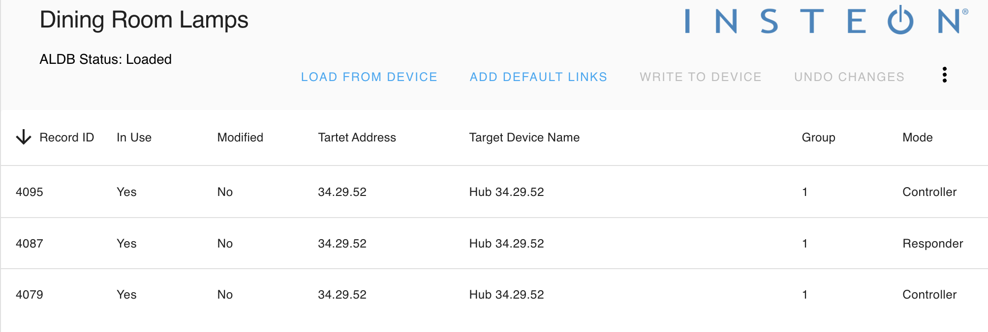
Thanks that clears up understanding for your example. I did reload several times, for each lamp dimmer but no additional links show up. and when I try to use. I also tried testing the scene using the developer tools > services > Insteon: Scene on and set the group to 100 to try on turn on both lams dimmers and doesn’t work. Is there a log that I can look at or try something else? Below are screenshots of my ALDB for the modem and each lamp dimmer.


FYI, there is a problem loading properties and ALDB for battery-operated devices and the same issue may be impacting modems. The error in the logs will look like this:
2022-05-07 21:04:00 ERROR (MainThread) [homeassistant.components.websocket_api.http.connection] [548235660208] Error handling message: Unknown error (unknown_error)
Traceback (most recent call last):
  File "/usr/src/homeassistant/homeassistant/components/websocket_api/decorators.py", line 27, in _handle_async_response
    await func(hass, connection, msg)
  File "/usr/src/homeassistant/homeassistant/components/insteon/api/properties.py", line 247, in websocket_load_properties
    result, _ = await device.async_read_config(read_aldb=False)
TypeError: cannot unpack non-iterable ResponseStatus object
The error in the UI will look like this:

There is a good chance the read request worked (or will work the next time the device wakes up) so the error message is a false alarm. I am working on a solution.
This issue is being tracked here: Unable to Load/Write from/to Device in Insteon integration page for battery devices and modems · Issue #71510 · home-assistant/core (github.com)
That is surprising that the modem received the links but the device did not. You could manually add the responder links if you want to now that you know what the data fields should look like.
@teharris1 … thanks for the detailed information on group numbers. That is exactly what I thought and suspected and in fact it is why I used “10” as my starting point.
Now I could not find a “decent” way to get access to the ALDB database except by developing sensor(s) to handle the insteon_devices.json file.
If there is a better way, please tell me but this leads to a few issues:
-
insteon_devices.jsonis stored in the root config. There is no way in REST sensor to get to that. - REST sensor is the only way to set
json_attributes_pathwhich is required to get into the data - command line sensor (i.e.
cat insteon_sensor.json) is no good because you cannot setjson_attributes_path
So The only thing I have been able to do to accomplish some nice Lovelace screens and sensors with this data is to (hack warning!!!) copy insteon_devices.json to a path that can be reached by REST.
Is there something I am missing where I can get access to these things?
When you say access to the ALDB, what are you trying to do? I don’t expose the ALDB directly in HA other than via the services and the UI panel. So what is the purpose of accessing the ALDB directly?
Well, if the GUI for the Insteon control panel because the total solution great. But in the meantime, I cannot do things like have a list of all the currently defined scenes. Nor I can I get a list of the devices in those scenes.
Personally, I prefer to be able to work with the data in Lovelace or other GUI components and not rely on what is handed to me. I would like to be able to develop my own ways of doing things.
OK. Well, let me think about this and see what can be done to expose more of the underlying elements of the device to scripts, etc. safely. Right now that is not on the roadmap but I can get some ideas on that.
Thanks. And I understand the need for the word “safely”. Just to point out that nothing I am putting together would be to change the ALDB (or insteon_devices.json) in any way except using the standard HA services. It is to be able to view them.
Think … I would love to have a input select populated with insteon scene numbers (… > 10). And I select it and another card appears with all the entities in that group. This is how people (I believe) want to work.
As in … let me see what is in that Insteon scene … oh, I need to add the “backyard flood lights at 50% to that” …
like this right now which I have. I am about to write the next step, given selecting one of those a card appears with all the devices in that scene.

That worked, so thanks again for that detailed explanation of the default links and groups. I have more confidence to use HA to have more power then I had before. 2 more questions, my insteon i_o_link for the garage seems to be in the reverse state, right now it’s closed but the sensor says open. When I open the garage it shows closed. Second question is how do you delete an insteon device?, I’ve removed a few switches and lamp dimmers and replaced with different technology but don’t see a way to delete the insteon devices. thanks!