slipx06
January 27, 2026, 9:09am
634
Everything looks good. Please paste your full card config, preformatted like the example below. Also make sure the entity is load_frequency_192
entities:
  use_timer_248: switch.sunsynk_toggle_system_timer
  priority_load_243: switch.sunsynk_toggle_priority_load
  day_battery_charge_70: sensor.sunsynk_day_battery_charge
  day_battery_discharge_71: sensor.sunsynk_day_battery_discharge
  day_load_energy_84: sensor.sunsynk_day_load_energy
  day_grid_import_76: sensor.sunsynk_day_grid_import
  day_grid_export_77: none
  day_pv_energy_108: sensor.sunsynk_day_pv_energy
  inverter_voltage_154: sensor.sunsynk_inverter_voltage
  load_frequency_192: sensor.sunsynk_load_frequency
  inverter_current_164: sensor.sunsynk_inverter_current
  inverter_power_175: sensor.sunsynk_inverter_power
ja500001
January 27, 2026, 10:48am
635
thanks @slipx06 , here is my card
cardstyle: full
wide: true
large_font: false
show_solar: true
show_battery: true
show_grid: true
center_no_grid: false
card_height: 100%
card_width: 100%
decimal_places: 1
decimal_places_energy: 1
dynamic_line_width: true
max_line_width: 4
min_line_width: 1
inverter:
  modern: false
  colour: "#9e9e9e"
  autarky: power
  model: sunsynk
  auto_scale: true
  three_phase: false
  navigate: ""
  label_autarky: ""
  label_ratio: ""
battery:
  show_daily: true
  invert_power: false
  show_remaining_energy: true
  remaining_energy_to_shutdown: false
  invert_flow: true
  energy: 30000
  count: 1
  soc_decimal_places: 1
  max_power: 30000
  auto_scale: false
  soc_end_of_charge: 100
  shutdown_soc: 10
  dynamic_colour: true
  navigate: https://blasta.eu.solar-assistant.io/
battery2:
  energy: 0
  shutdown_soc: 20
  soc_end_of_charge: 100
  invert_power: false
  hide_soc: false
  colour: "#ffc0cb"
  show_remaining_energy: true
  remaining_energy_to_shutdown: false
  show_absolute: false
  auto_scale: true
  dynamic_colour: true
  linear_gradient: true
  animate: true
  path_threshold: 100
  navigate: ""
  invert_flow: false
solar:
  show_daily: true
  mppts: 1
load:
  show_daily: true
  auto_scale: false
  dynamic_colour: true
  dynamic_icon: true
  show_aux: false
  additional_loads: 0
grid:
  show_daily_buy: true
  show_daily_sell: true
  show_nonessential: true
  grid_name: Octopus
  invert_flow: false
  auto_scale: true
  energy_cost_decimals: 1
  additional_loads: 0
type: custom:sunsynk-power-flow-card
entities:
  use_timer_248: switch.not_connected_use_timer
  priority_load_243: sensor.not_connected_load_power_essential
  inverter_voltage_154: sensor.not_connected_ac_output_voltage
  inverter_current_164: sensor.not_connected_battery_current
  inverter_power_175: sensor.not_connected_battery_power
  grid_load_freq_192: sensor.deye_sunsynk_sol_ark_ac_output_frequency
  grid_connected_status_194: sensor.not_connected_grid_energy_out_compensation
  day_battery_charge_70: sensor.not_connected_battery_energy_in
  day_battery_discharge_71: sensor.not_connected_battery_energy_out
  battery_voltage_183: sensor.not_connected_battery_voltage
  grid_power_169: sensor.not_connected_grid_power_ct
  day_grid_import_76: sensor.not_connected_grid_energy_in
  day_grid_export_77: sensor.not_connected_grid_energy_out
  grid_ct_power_172: sensor.not_connected_grid_power_ct
  essential_power: sensor.not_connected_load_power_essential
  nonessential_power: sensor.not_connected_load_power
  day_pv_energy_108: sensor.gc150146_0_energy_today
  pv1_power_186: sensor.solar_panels_current_power
  energy_cost_buy: sensor.octopus_energy_electricity_22j0552939_1800030000010_current_rate
  grid_voltage: sensor.not_connected_grid_voltage
  energy_cost_sell: >-
    sensor.octopus_energy_electricity_22j0552939_1800061472306_export_current_rate
  prog1_time: select.not_connected_time_point_1
  battery_current_191: sensor.not_connected_battery_current
  battery_current_direction: sensor.not_connected_battery_current
  battery_temp_182: sensor.not_connected_battery_temperature
  battery_power_190: sensor.not_connected_battery_power
  prog2_time: select.not_connected_time_point_2
  prog3_time: select.not_connected_time_point_3
  prog4_time: select.not_connected_time_point_4
  prog5_time: select.not_connected_time_point_5
  prog6_time: select.not_connected_time_point_6
  battery_soc_184: sensor.deye_sunsynk_sol_ark_battery_state_of_charge
  battery_status: number.not_connected_battery_absorption_charge_voltage
  prog6_charge: switch.not_connected_grid_charge_point_6
  prog5_charge: switch.not_connected_grid_charge_point_5
  prog4_charge: switch.not_connected_grid_charge_point_4
  prog3_charge: switch.not_connected_grid_charge_point_3
  prog2_charge: switch.not_connected_grid_charge_point_2
  prog1_charge: switch.not_connected_grid_charge_point_1
  prog1_capacity: number.not_connected_capacity_point_1
  prog2_capacity: number.not_connected_capacity_point_2
  prog3_capacity: number.not_connected_capacity_point_3
  prog4_capacity: number.not_connected_capacity_point_4
  prog5_capacity: number.not_connected_capacity_point_5
  prog6_capacity: number.not_connected_capacity_point_6
  aux_connected_status: select.not_connected_generator_connected_to_grid_input
  essential_load1: sensor.not_connected_load_power
  day_load_energy_84: sensor.not_connected_load_energy
  grid_ct_power_total: sensor.not_connected_grid_power
  non_essential_load1: sensor.not_connected_load_power_non_essential
title: Energy Flow
title_size: 16px
grid_options:
  columns: full
  rows: 8
I am not sure why there are so many sensors listed as “sensor.not_connected_xxx”, their values are still be displayed on the card itself though …
slipx06
January 27, 2026, 11:11am
636
@ja500001 This sensor is wrong grid_load_freq_192: sensor.deye_sunsynk_sol_ark_ac_output_frequency . Change it to load_frequency_192: sensor.deye_sunsynk_sol_ark_ac_output_frequency
ja500001
January 27, 2026, 11:34am
637
Yes, that’s fixed it, thank you so much for spending the time to help me on this, absolute GOAT!
1 Like
antonical
February 28, 2026, 10:00pm
638
HI Thank you for all your hard work in producing this power flow card.
Is it possible to support multiple sunsynk inverters and batteries on one power flow card. If so how?
Setup will shortly be:
Inverter 1 G98 Sunsynk Acure with 32kWh battery CT on a sub circuit.
Is there a way to config the power flow card to show this type of setup. Essentially the G98 Inverter is AC Coupled the only ‘grid’ it sees is the grid peresented by the upstream Inverter 2. Inverter 2 has the main incoming grid feed connected to its grid port. CT on its live incomer and zero export across both inverters.
Any help figuring this out is appreciated.
Just posting the current config and card in case it helps others. The modbus data comes from a WaveShare RS485 to ETH (B) POE adaptor wired into the RS485/CAN port using a splitter. The Battery uses the CAN and the WaveShare uses the RS485. Seems rock solid in terms of data.
# Sunsynk Acure 3.6
  - name: "sunsynk_direct"
    type: tcp
    host: 192.168.0.131
    port: 8899
#    delay: 5                   # Increased: 5s delay after connecting to let the bus settle
#    timeout: 10                # Increased: Give the picky 3.6 unit 10s to reply
#    message_wait_milliseconds: 250 # Gap between messages to prevent "Extra Data" errors
#    retries: 3
    switches:
      - name: "direct_modbus_toggle_system_timer"
        slave: 1
        address: 248
        write_type: holding
        command_on: 255
        command_off: 0
        verify:
          address: 248
          input_type: holding
          state_on: 255
          state_off: 0
      - name: "direct_modbus_toggle_priority_load"
        slave: 1
        address: 243
        write_type: holding
        command_on: 1
        command_off: 0
        verify:
          address: 243
          input_type: holding
      - name: "direct_modbus_grid_charge_1"
        unique_id: "sunsynk_chg_slot_1"
        slave: 1
        address: 274
        command_on: 1
        command_off: 0
        verify:
          address: 274
          input_type: holding
          state_on: 1
          state_off: 0
    sensors:
      - name: "direct_modbus_inverter_voltage"
        slave: 1
        address: 154
        scale: 0.1
        precision: 1
        unit_of_measurement: "V"
        device_class: voltage
      - name: "direct_modbus_load_frequency"
        slave: 1
        address: 192
        scale: 0.01
        precision: 2
        unit_of_measurement: "Hz"
        device_class: frequency
      - name: "direct_modbus_inverter_current"
        slave: 1
        address: 164
        scale: 0.01
        precision: 2
        unit_of_measurement: "A"
        device_class: current
      - name: "direct_modbus_inverter_power"
        slave: 1
        address: 175
        unit_of_measurement: "W"
        device_class: power
      - name: "direct_modbus_grid_acrelay_status"
        slave: 1
        address: 194
      - name: "direct_modbus_runstatus"
        slave: 1
        address: 59
      - name: "direct_modbus_battery_etoday_charge"
        slave: 1
        address: 70
        scale: 0.1
        precision: 2
        unit_of_measurement: "kWh"
        device_class: energy
        state_class: total_increasing
      - name: "direct_modbus_battery_etoday_discharge"
        slave: 1
        address: 71
        scale: 0.1
        precision: 2
        unit_of_measurement: "kWh"
        device_class: energy
        state_class: total_increasing
      - name: "direct_modbus_grid_power"
        slave: 1
        address: 169
        unit_of_measurement: "W"
        device_class: power
      - name: "direct_modbus_grid_etoday_from"
        slave: 1
        address: 76
        scale: 0.1
        precision: 2
        unit_of_measurement: "kWh"
        device_class: energy
        state_class: total_increasing
      - name: "direct_modbus_grid_etoday_to"
        slave: 1
        address: 77
        scale: 0.1
        precision: 2
        unit_of_measurement: "kWh"
        device_class: energy
        state_class: total_increasing
      - name: "direct_modbus_grid_power_ct"
        slave: 1
        address: 172
        unit_of_measurement: "W"
        device_class: power
      - name: "direct_modbus_load_daily_used"
        slave: 1
        address: 84
        scale: 0.1
        precision: 2
        unit_of_measurement: "kWh"
        device_class: energy
        state_class: total_increasing
      - name: "direct_modbus_aux_power"
        slave: 1
        address: 166
        unit_of_measurement: "W"
        device_class: power
      - name: "direct_modbus_pv_mppt0_power"
        slave: 1
        address: 186
        unit_of_measurement: "W"
        device_class: power
      - name: "direct_modbus_pv_mppt1_po```wer"
        slave: 1
        address: 187
        unit_of_measurement: "W"
        device_class: power
      - name: "direct_modbus_pv_mppt0_voltage"
        slave: 1
        address: 109
        scale: 0.1
        precision: 1
        unit_of_measurement: "V"
        device_class: voltage
      - name: "direct_modbus_pv_mppt0_current"
        slave: 1
        address: 110
        scale: 0.1
        precision: 1
        unit_of_measurement: "A"
        device_class: current
      - name: "direct_modbus_pv_mppt1_voltage"
        slave: 1
        address: 111
        scale: 0.1
        precision: 1
        unit_of_measurement: "V"
        device_class: voltage
      - name: "direct_modbus_pv_mppt1_current"
        slave: 1
        address: 112
        scale: 0.1
        precision: 1
        unit_of_measurement: "A"
        device_class: current
      - name: "direct_modbus_pv_etoday"
        slave: 1
        address: 108```
        input_type: holding
        scale: 0.1
        precision: 2
        unit_of_measurement: "kWh"
        device_class: energy
        state_class: total_increasing
      - name: "direct_modbus_grid_voltage"
        slave: 1
        address: 150
        scale: 0.1
        precision: 1
        unit_of_measurement: "V"
        device_class: voltage
      - name: "direct_modbus_battery_soc"
        slave: 1
        address: 184
        unit_of_measurement: "%"
        data_type: uint16
        device_class: battery
      - name: "direct_modbus_battery_voltage"
        slave: 1
        address: 183
        input_type: holding
        unit_of_measurement: "V"
        scale: 0.01
        precision: 2
        device_class: voltage
      - name: "direct_modbus_battery_temperature"
        slave: 1
        address: 182
        input_type: holding
        unit_of_measurement: "°C"
        scale: 0.1
        offset: -100.0
        precision: 1
        device_class: temperature
      - name: "direct_modbus_battery_current"
        slave: 1
        address: 191
        scale: -0.01          # Added minus to flip the sign
        precision: 2
        unit_of_measurement: "A"
        data_type: int16
        device_class: current
      - name: "direct_modbus_battery_power"
        slave: 1
        address: 190
        input_type: holding
        scale: -1             # Added scale to flip the sign
        unit_of_measurement: "W"
        data_type: int16
        device_class: power
      - name: "direct_modbus_battery_direction"
        slave: 1
        address: 189
        input_type: holding
      - name: "direct_modbus_battery_soc1_cap"
        slave: 1
        address: 268
        input_type: holding
        scan_interval: 30

template:
  - number:
      - name: "Sunsynk Battery Limit"
        state: "{{ states('sensor.direct_modbus_battery_soc1_cap') | int(20) }}"
        step: 1
        min: 0
        max: 100
        unit_of_measurement: "%"
        set_value:
          - action: modbus.write_register
            data:
              hub: sunsynk_direct
              slave: 1
              address: 268
              value: ["{{ value | int }}"]
Maybe it’s possible to have 2 instances of the Power Flow Card
Cheers
Nice, I’ve been looking for an all-in one card that supports both energy and power instead of just focusing on one metric at a time, while also supporting loads and such.
llaforest
March 13, 2026, 10:05am
641
Hi, I’ve been using this card with a Luxpower 12k inverter in a whole-house backup configuration (grid + generator + solar + battery). During grid outages the backup generator takes over, but the card has no way to represent generator as an AC input source — it currently only supports generator as an AUX output.
I opened a GitHub feature request for this: Backup generator as grid-replacement power source · Issue #808 · slipx06/sunsynk-power-flow-card · GitHub
The idea is to allow choosing the AC source displayed in the grid branch — grid (default, no change), generator (for off-grid systems), or auto (swap between grid and generator based on a status entity). Would love to hear if others have a similar setup and would find this useful.
Roman-F-EF
April 3, 2026, 12:22pm
642
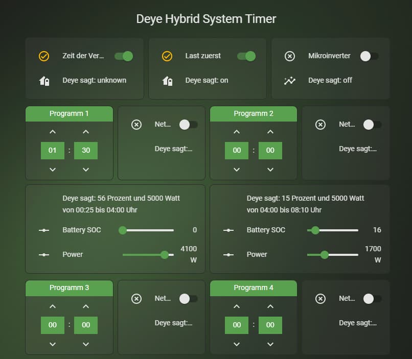
“Deye sagt” ist die jeweilige Darstellung der gelesenen Register. Es entfällt somit eine vorherige Abfrage der eingestellten Werte.
Roman-F-EF
April 3, 2026, 12:25pm
643
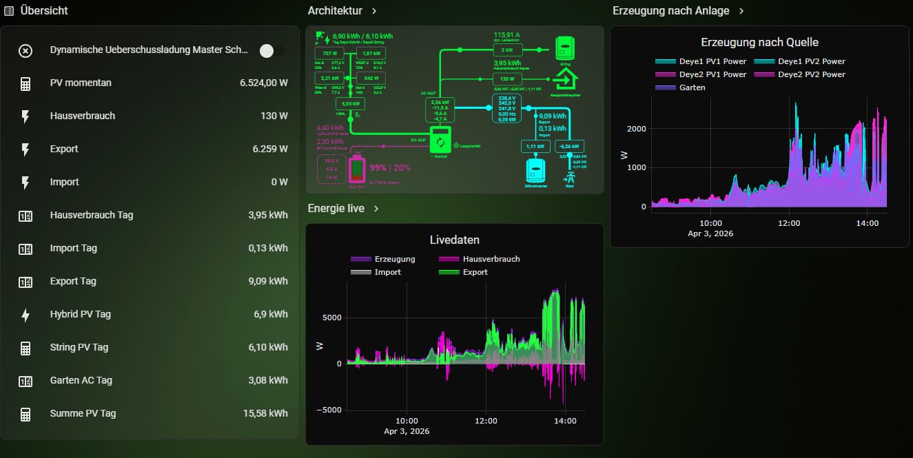
System mit 3 Wechselrichtern.