I want to understand this issue so as not to ask more questions
We have concluded together that modbus_controller doesn’t give any data because it expects answer from 81. Right?
so this line doesn’t return anything:
float vv = (data[3]+data[4])* 0.1;
Right? Dead end.
You have to work with uart_debug.
Code in your post46 is where you need to work on.
Use the piece of code in my post58 in your uart_debug and get all those registers same way from 0x52 (bytes[4]) to 0x59 (bytes[13])
By the way, you only posted a screenshot of modbus registers. There are others, writeable registers?
I can post all the documentation that I have
Don’t be shy ![]()
[22:33:46][D][uart_debug:114]: <<< 51:03:10:00:01:00:01:00:00:00:00:00:00:0D:00:00:00:00:00:F7:C9
[22:33:46][D][main:047]: Response data only had 21 bytes!!
I can’t do this, the forum doesn’t allow me to upload files here
Sorry my mistake( serious brain fart). Every register is 2 bytes, so 21 is correct.
if (bytes.size() == 21) {
int chargingMosStatus = bytes[3] + bytes[4];
id(cms).publish_state(chargingMosStatus);
int dischargeMosStatus = bytes[5] +bytes[6];
id(dms).publish_state(dischargeMosStatus);
I’m not going to open files from that source, but have a look if there is writeable register for modbus id.
Second brain fart… ![]()
thanks, I’ll find the time and get on with it
You are almost there…
were you able to get this to work? I have a 100balance bms as well
uart:
  - id: uart_0
    baud_rate: 9600
    tx_pin: D2
    rx_pin: D3

    debug:
      direction: BOTH
      dummy_receiver: true
      after:
         delimiter: "\n"
      sequence:
          - lambda: |-
              UARTDebug::log_hex(direction, bytes, ':');
              ESP_LOGD("main", "Response data only had %d bytes!!", bytes.size() );
              std::string str(bytes.begin(), bytes.end());

              if (bytes.size() == 27) {
               ESP_LOGD("main", "Response data %d", bytes[0]);
               ESP_LOGD("main", "Response data %d", bytes[1]);

               int tv = (bytes[3] << 8) | bytes[4];
               id(tbv).publish_state(tv);

               int curent = ((bytes[5] << 8) | bytes[6]) - 30000;
               id(cd).publish_state(curent);

               int so = (bytes[7] << 8) | bytes[8];
               id(soc).publish_state(so);

               int di = (bytes[23] << 8) | bytes[24];
               id(dif).publish_state(di);

              }
modbus:
  - id: modbus0
    uart_id: uart_0
    send_wait_time: 1000ms
    disable_crc: true

modbus_controller:
  - id: bms
    address: 0x81
    modbus_id: modbus0
    command_throttle: 5000ms
    update_interval: 2s
    setup_priority: -20

sensor:
  - platform: template
    id: tbv
    name: TolalVoltage # 0x38 register
    filters:
      - multiply: 0.1
    accuracy_decimals: 1
    unit_of_measurement: "V"

  - platform: template
    id: cd
    name: CurrentData # 0x39 register
    filters:
      - multiply: 0.1
    accuracy_decimals: 1
    unit_of_measurement: "A"

  - platform: template
    id: soc
    name: SOC # 0x3A register
    filters:
      - multiply: 0.1
    unit_of_measurement: "%"
    accuracy_decimals: 0

  - platform: template
    id: dif
    name: DiffVoltage # 0x42 register
    filters:
      - multiply: 0.001
    accuracy_decimals: 3
    unit_of_measurement: "V"


  - platform: modbus_controller
    modbus_controller_id: bms
    id: custom
    custom_command: [0x81, 0x03, 0x00, 0x38, 0x00, 0x0B]  # 0x38 first register to read, 0xB = 11 register count (27 byte response)
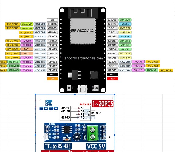
Thanks!! Did you wired the bms via UART port directly to ESP32 board ( TX pin 6 and RX pin 5)? Sorry the original thread mentioned RS485. If it’s RS485… i’m guessing you’ll need the TTL → RS485 board in between?
I’m using a UART RS485 converter
Nope, not with the default esphome RS485 component


