JoyOnWay Spa Control

Hi @old-man,

Thank you for testing the integration so extensively and providing such detailed reports!

Regarding your observations about the jets and status indicators, this is actually fully expected and by design.

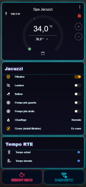
Jets and Status Separation:

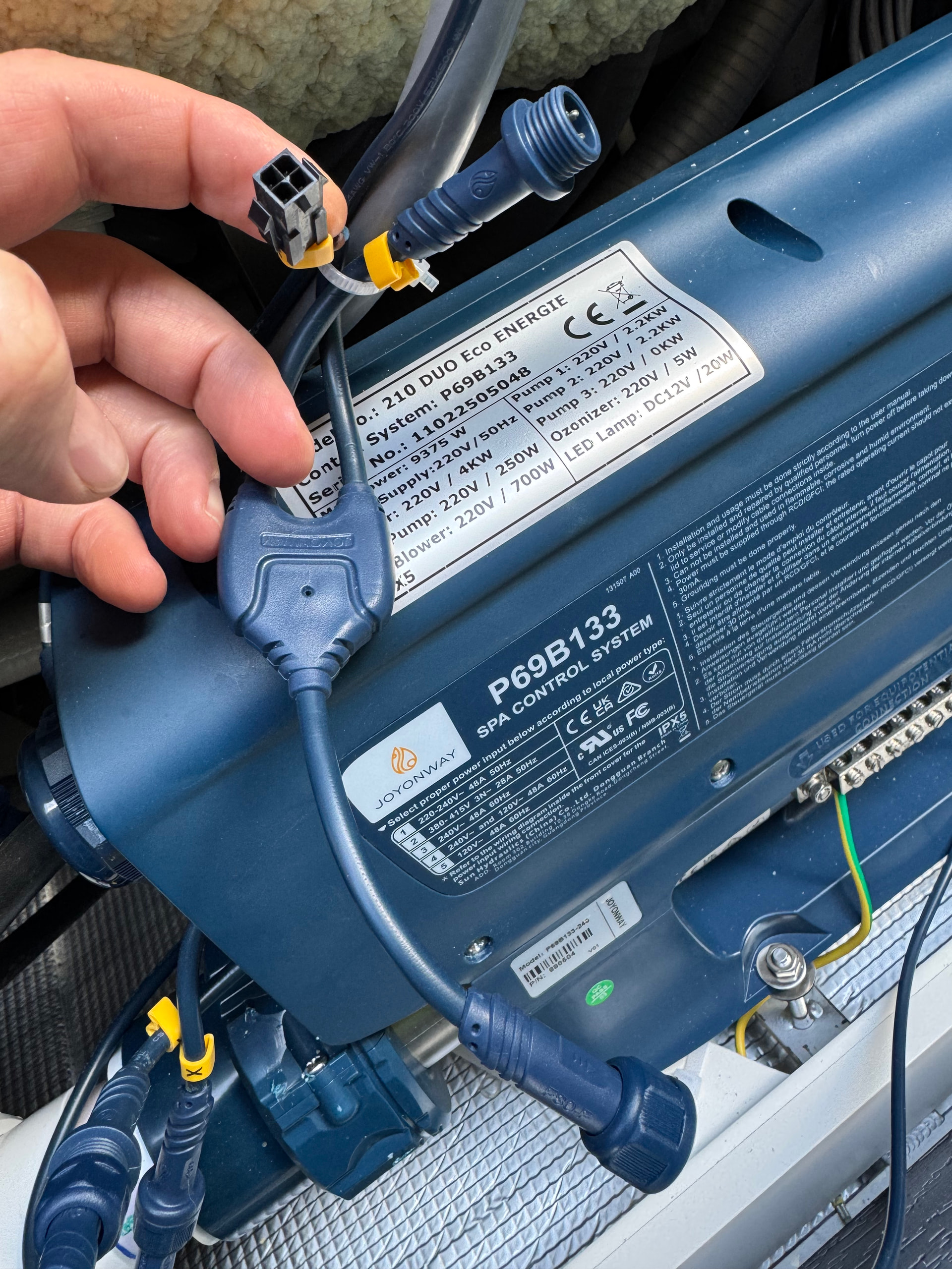
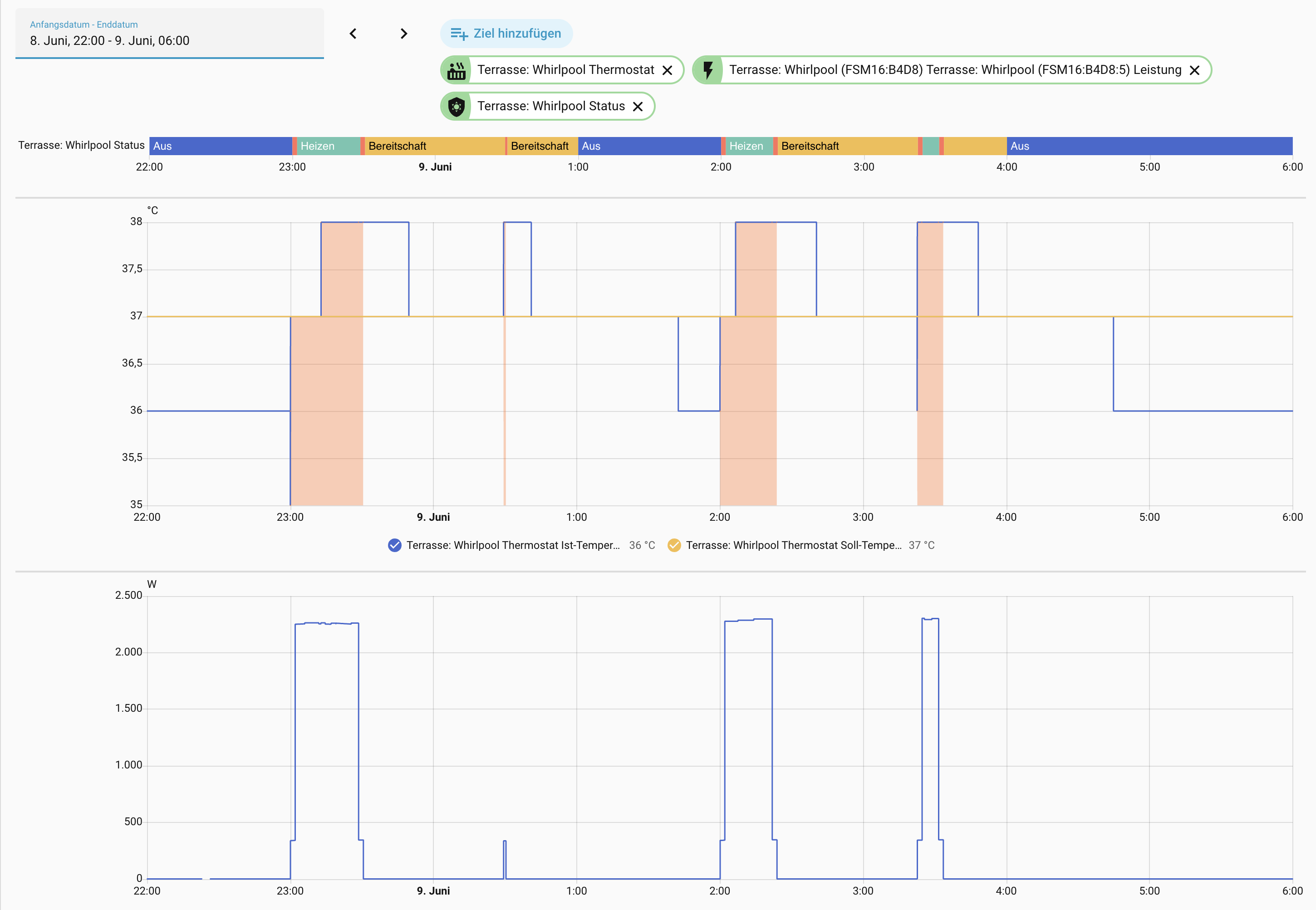
The controller separates background maintenance tasks (heating, filtration, ozone cycles) from manual massage demands (jets). Since both share the same physical two-speed pump motor, the motor runs whenever either demand is active:

  • When a background program is running, the pump runs at Low speed, but the Jets indicator correctly shows Off because you did not manually turn them on.
  • If you manually turn the jets on to Low, the physical pump continues at Low speed, but the Jets status updates to Low in Home Assistant.
  • If you turn the jets Off while a background program is still active, the Jets indicator reverts to Off, but the pump continues running at Low speed to complete the background cycle.
  • If the background cycle completes while the jets are manually active, the pump stays on until you turn the jets Off or the safety timeout expires.

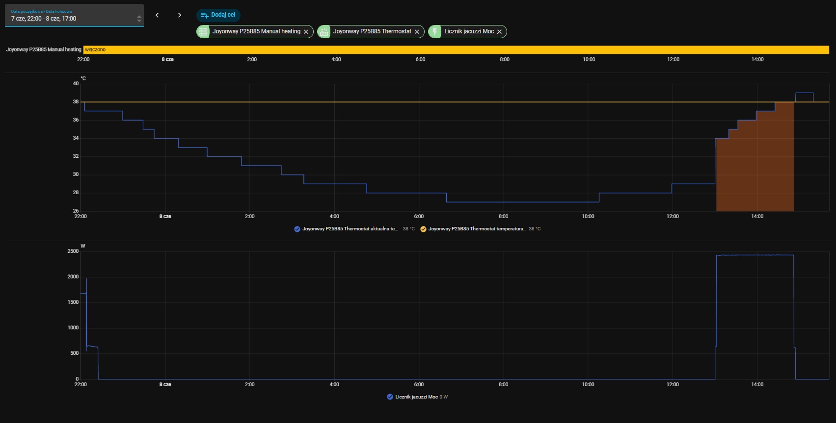
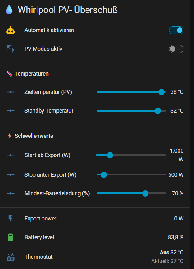
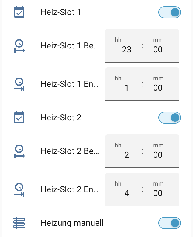
Manual Heating Switch:

The P25B85 has two layers of heater control:

  • Before you can manually control the heater, the spa must be in Manual Heating mode. You can toggle this on the control panel or via the Manual Heating switch in Home Assistant.
  • The main Heater switch in Home Assistant is locked (unavailable) unless the spa is in Manual Heating mode. Trying to toggle the heater while in Auto Heating mode causes the switch to snap back because the controller rejects the command.
  • Once Manual Heating mode is enabled and the target setpoint is set higher than the water temperature, the Heater switch becomes fully available in Home Assistant and can be toggled on/off independently.

This logical separation allows the Home Assistant UI and display panel to accurately reflect your manual intents without background utility tasks interfering, even though both functions share the same physical two-speed pump motor.

Thank you again for all your help with testing!

Hi everyone,

I am happy to announce the release 1.0.0 of the Joyonway Spa Integration (P25B85) :rocket:

This integration provides local-push support for the Joyonway P25B85 spa controller (tested with PB554 display) connected via an RS485 TCP bridge (such as the Elfin EW11).

:glowing_star: Key Features

  • Real-time Local Push: Instant status updates via persistent TCP stream listening.
  • Full Thermostat Control: Target temperature setpoint controls (10°C to 40°C) with slider debouncing to prevent RS485 bus congestion.
  • Physical Component Control: Switches for the Light, Heater, Ozone generator, and Blower.
  • Dual-Speed Pump Control: Speed control for the Jets pump (off / low / high) exposed as a fan entity.
  • Schedule management: View and configure start/end times and enables for all 4 heating/filtration schedule slots directly from Home Assistant.
  • Clock Auto-Sync: native automatic clock drift synchronization (runs with drift >30s and a 1-hour cooldown).
  • Diagnostic Sensors: Exposed raw byte registers, connection status, and unmapped register tracking for advanced troubleshooting.

Contributions are very welcome! Whether it is reverse-engineering new controller models, submitting bug fixes, improving translations, or anything else, do not hesitate to submit your contribution.

Thank you to everyone who helped test the early versions, especially @KDy, @christopheknap & @old-man! If you encounter any bugs, feel free to open an issue on GitHub or reply to this thread of course :slight_smile:

Replying to myself with so far zero progress unfortunately.

I started by removing the splitter on CN24 where the PAC was and plugged only the W610. The display is alone on CN23. With that setup, and with the W610 at 115200 bauds, @Gaet78’s integration doesn’t detect the SPA.

Then I tried the opposite with same result, the integration doesn’t see the SPA.

I tested both frames dumps with @christopheknap’s frame analyzer that detected nothing. Do you see the frames that I normally shared through the tool?

The only thing I couldn’t test yet is putting both the display and W610 on CN23 with a splitter because my splitter doesn’t have the right connector at one end (male Molex where the PAC is connected) so I need to hack a new cable for my W610 with a female Molex connector.

About the W610, just checking if the LEDs state are what I should expect: Power, Link and RXD are all stable lit, Work flashes with regular 1-2s frequency.

Quick round-up, several things landed at once.

Congrats on the 1.0.0 release, alexbde. The P25B85 integration reaching a stable version is great for the whole community. Local push, thermostat with slider debouncing, dual-speed jets as a fan entity, the 4 schedule slots, and the diagnostic raw-register sensors, that is a complete package. The sync frame alignment from PR #18 was the right call for the single-client bus. One friendly note for anyone upgrading: the native clock auto-sync (drift >30s, 1h cooldown) belongs to the same feature family that overwrote KDy's config back in May, so anyone bitten then should keep an eye on it after updating and confirm the guards behave on their firmware. For reference, Alex runs an Elfin EW11, which adds a third known-good bridge alongside the W610 and Yannickt26's ZLAN5143D.

Frame Analyzer 404 is fixed. The app is back online at Joyonway Frame Analyzer V4.2 (V4.2). Thanks marcgit198 for the report. Scope reminder so nobody loses time: the live decoder handles P23B32 V2 only (delimiters 0x1A...0x1D at 38400 baud). P69B133 is a Balboa-like family (0x7E...0x7E at 115200 baud), documented as a profile, not yet an active decoder in the app. An empty result on a P69B133 capture is expected, not a bug.

New diagnostic tool for everyone, especially P69B133 owners. I looked closely at the kind of captures coming from P69B133 setups, and several contain no valid Joyonway frames at all: no 0x7E, no 0x1A, just a repeating non-spa byte pattern. That is not an analyzer problem, the capture itself is unusable at the source. Two usual causes: wrong baud rate (the bridge delivers desynchronized bytes), or another device polluting the bus, a heat pump wired on the same RS485 lines being the prime suspect.

To stop guessing, here is a tiny local script that tells you in 5 seconds whether your capture is decodable and, if not, why:
https://raw.githubusercontent.com/KnapTheBuilder/joyonway-frame-analyzer/main/tools/joyonway_diag.py

Usage:
python3 joyonway_diag.py capture.bin

It counts the protocol delimiters and gives a verdict. No network, nothing sent anywhere, pure local Python 3, no dependencies. Recommended procedure:

  1. Capture 60s: nc YOUR_BRIDGE_IP 8899 > capture.bin (only one TCP client on the bridge at a time).
  2. Run joyonway_diag.py on it.
  3. If it says no valid frames, change the baud (try 9600, 38400, 115200) and recapture. The right baud makes 0x7E appear for the P69B133, or 0x1A for the P23B32.
  4. If 0x7E still never shows up, unplug the heat pump from the bus, keep the bridge alone, recapture. If the junk pattern disappears, the PAC was the cause.

mfo38 and marcgit198 (P69B133). That is exactly your situation. mfo38, your W610 LEDs are fine (Power/Link/RXD steady, Work blinking 1-2s means the bus is talking and the bridge is receiving), so the issue is upstream of the bridge: baud or PAC. Run joyonway_diag.py on your dump first, it will point you straight to the cause. And since the Contribute button sends captures anonymously by design, I cannot match a contributed capture back to a username, so once the script confirms a clean capture with 0x7E present, attach it directly here or open an issue on the analyzer repo and I will trace the frame layout with you.

old-man (P25B85), heating via HA without a program. The toggle snapping back is the controller refusing a write it considers invalid in that state. On Joyonway, the heater is generally not a standalone switch, the resistance only runs when filtration/circulation is active and a heat demand exists. Make sure filtration is running first, then request heat. Confirm on real power draw too, not just the controller flag, the heating bit often means demand/authorization, not actual resistance activity. With Alex's 1.0.0 out, a clean reinstall may also clear the state-tracking glitches.

Hi Christophe,

thank you very much! Some quick additions:

  • Clock sync: All writing commands are disabled by default now. The clock sync needs to be activated by the user explicitly. If you do and experience any issue (or success), please report! I will also do more testing in this direction in the next days
  • Heater snap back: This happened in a previous version where the manual heating switch was always enabled. I captured the manual heating mode bytes in the meantime, and make the heating switch unavailable when the manual heating mode is disabled (that's analogous to how the spa display behaves). So this should no longer happen :+1:
  • I really love how you are evolving into an expert of the Joyonway frames. A few more weeks and we don't need the frame analyzer anymore - you will simply be capable of reading the frames like natural language :grin:

Best,
Alex

Hi again,

I had a few late night thoughts. A few weeks ago, I was super desperate and about to spend a lot of money on the official Wi-Fi module. Thanks to the community and the progress in this thread, I got local-push working instead.

@christopheknap, @Yannickt26, you mentioned in an earlier post the mid-term goal of a unified integration that auto-detects the model. I absolutely love this vision, and I think it is the best path forward for all of us. Having a single, polished repository would make it much easier for new users to get started and for us to maintain it together.

I have a unique opportunity that might help is achcelerate this: due to Google changing the Gemini conditions, I have a large allocation of Gemini AI credits that will expire on June 18, 2026. I would love to "donate" these credits to our shared project by using my agentic coding assistant to do the heavy lifting of the implementation. With your deep understanding of the frames and the analyzer tool, I can focus the AI on translating those protocol insights directly into HA code to support the P23B32 and P20B29 models in an unified modular adapter pattern.

Because the AI is very fast at analyzing the spa protocols, matching patterns, and implementing the HA components, we could:

  1. Collaborate on the unified integration (we can use my repo as the base, or move it under a joint GitHub organization if you prefer).
  2. Use the AI to implement and fully test the P23B32/P20B29 adapter logic next to the P25B85 structure.
  3. Align on a clean, robust, and HACS-compliant layout that works seamlessly for everyone.

Of course, this is a fully joint effort. I want to make sure we align on the architecture first, and I don't want to step on anyone’s toes or duplicate work.

Christophe, Yannick, how do you feel about this? Would you be open to collaborating on this unified codebase and letting me use the AI credits to wire up the P23/P20 integration profiles before June 18? This would be my way of giving something back to the community :slight_smile:

Looking forward to your thoughts!

Best,
Alex

Thanks for the script and all efforts you put into helping me get this to work.

Sad thing is, I’m almost out of options after my last tests. With PAC disconnected, I tried all the baud rates that you suggested and more, oddly enough only 57600 & 230400 produce a capture.bin where the .py script thinks it sees the 0x7E frames linked to the P69B133. But once uploaded on the frame analyzer, no valid frames are detected. Example:

Format detecte : binaire brut

========================================================

  JOYONWAY DIAG - resultat

========================================================

  Octets analyses        : 19568

  Taux 0xFF              : 4.4 %

  Taux 0x00              : 19.9 %

  Delimiteurs 0x7E       : 164   (P69B133 type Balboa)

  Debuts 0x1A / fins 0x1D: 0 / 1   (P23B32 V2)

  Motif 03 00 A0         : 0   (flux non-Joyonway / PAC)

--------------------------------------------------------

  PROTOCOLE DETECTE : type Balboa / P69B133 (0x7E).

  -> Capture exploitable cote profil Balboa.

  -> Baud attendu : 115200. Integration de reference : Gaet78.

Conditions during the capture:

  • W610 alone on CN24 on the splitter, display alone on CN23

  • No action performed on the display while capturing

  • Joyonway Spa Controller App disconnected

  • But SPA display still connected to Wifi (and therefore Alibaba cloud)

So what is going on ? Is my cable faulty ?

Apart from baud rate, is my W610 misconfigured ? I tried so many different settings on it. Putting print screens of all relevant settings.

The last thing I want to try once I have the needed molex connector is plugging the W610 on one end of the splitter, the display on the other end and the splitter on CN23, nothing on CN24.

If you have other suggestions, I am a taker. Thanks in advance.

Don't give up yet, your tests actually tell us a lot. And first, a correction on my own script: the 57600 / 230400 results are a FALSE POSITIVE, my fault. 164 occurrences of 0x7E over 19568 bytes is only 0.84%, basically the rate you'd get by pure chance (0.39%). A real Balboa stream would show delimiters at around 3 to 5%, regular and evenly spaced, framing packets of consistent length. Yours are scattered random 0x7E in noise. So the analyzer is right to reject them, and my script was too lenient. I've tightened it to check delimiter DENSITY, not just a raw count, so it no longer gives that false hope. Updated version is at the same link.

So: 115200 is the correct baud for the P69B133, not 57600 or 230400. Your UART config confirms it (115200 8N1, 485 mode on), and your network side is fine (TCP server, port 8899, STA, transparent). Nothing wrong there.

The most likely problem is the RS485 wiring itself, and the answer comes straight from @Gaet78's wiring doc for the P69B133. The bus connector is the 4-pin ROUND blue bayonet connector (the display port), not the black rectangular Molex. The four wires map like this:

Orange = RS485 Data- -> W610 port B
Brown = RS485 Data+ -> W610 port A
Red = +12V -> NOT connected
Black = Ground -> NOT connected

Only two wires matter: Orange to B, Brown to A. Leave Red (+12V) and Black (Ground) unconnected. If A and B are swapped, or you tapped the wrong pins, the W610 reads exactly the kind of noise you've been getting at every baud rate. An A/B swap is the single most common RS485 mistake and harms nothing electrically, so if Orange->B / Brown->A gives nothing, just swap A and B and recapture before changing anything else.

Where to tap, from Gaet78's doc, two options:

  • Option 1 (recommended): the RS485 bus has a free connector, likely meant for the WiFi module. If you have a dead old control panel, reuse its connector, no cable to cut, warranty preserved. This 4-pin type is hard to source though.
  • Option 2: on the mainboard there are two connectors, CN23 and CN24. The panel sits on one, the other is free. The 4-pin connector there is more common and easier to find.

A plain Ethernet cable works very well from the spa connector to the W610, tested at 10 m, which lets you keep the W610 out of the damp spa zone. Gaet78's full wiring guide: [LIEN REPO GAET78]

One last thing: your PB563 panel has the WiFi transceiver built in, so keep the PAC disconnected while you test, to leave only one variable. So no, I don't think your cable is faulty and your W610 isn't really misconfigured. Fix the A/B wiring first, I'd bet that's the culprit.

mfo38,
How do you power the W610? I use a different bridge that’s connected direct to the connector, as the permissible voltages allow for a direct connection. But I don’t know how it works with the W610, and in particular, I don’t know how you power it. If you’re powering it from another source than the RS485 socket, e.g. an external power supply, you MUST have the GROUND connected.

KDy is right, and it's an important point I glossed over. My "leave Black/Ground unconnected" only holds if the W610 is powered FROM the bus itself (the Red +12V wire). In that case ground is already shared through the connector.

But if you power the W610 from a separate supply (external PSU, USB adapter, etc.), then you MUST connect the Ground (Black) wire between the spa bus and the W610. Without a common ground reference, the two devices float relative to each other and the RS485 link becomes unreliable, which produces exactly the noise you're seeing at every baud rate.

So, mfo38, the key question: how is your W610 powered?

  • Powered from the bus +12V (Red wire): ground already common, Black can stay unconnected. Just Orange->B, Brown->A.
  • Powered externally: connect Orange->B, Brown->A AND Black->GND on the W610. Skipping the ground here is very likely your whole problem.

The W610 takes 5-30V DC, so either way works, but the ground rule changes depending on which you chose. Thanks KDy for catching this.

I’m not giving up, not with you guys trying so hard to help :wink:

So you are most probably and hopefully on something.

Because I wasn’t sure I could power it on CN23 or CN24, my W610 is powered externally with the power adapter that came with it. I hacked a power extension cord and powered it on the controller board AUX port (where the PAC is also powered).

So I am definitely missing the GND connection on the W610. Hopefully that’s the cause of the randomness of my captured frames.

That being said, I’m not in front of it right now since it’s inside the SPA and I can’t open it right now, but looking at a picture I made few days ago, I don’t see a ground screw on my model:

That’s my model: RS485 to WiFi Converters | RS232 to WiFi Converters | Serial WiFi Converters

I see a ground screw on that one though: https://www.pusr.com/products/USR-W610-Qualcomm-version.html

So in my case just screw the GND coming from CN24 (or CN23) to the metal casing of the W610 ?

Setting:
Manual heating: ON
Heat slot 1: ON 22:00 - 6:00
Heat slot 2: ON 13:00 - 15:00

Between 10:00 PM and 6:00 AM, the heating didn't turn on properly.

At 1:00 PM, the heating turned on even though Manual heating mode was enabled.

Alex, old-man, could you check how it works for you?

I’ve turned off the manual heating and now control it via the schedule: 7 a.m. to 11 a.m. and 12 p.m. to 5 p.m. No issues—everything is running great.
Since yesterday, I’ve been using an automation to adjust the temperature based on PV surplus. That’s working well, too.
I’m really happy with it.

I checked again, and it's consistent and applies to both slot 1 and slot 2. Last night, it didn't turn on in slot 1 because the temperature probably didn't drop enough. But that's not a fault. The panel behaves the same, even after a factory reset. But then, why is there this manual/auto mode switch? This is illogical on Joyonway's part.

When switching on the manual heating, you can start the heating independently of the program using the control unit or via HA—provided the temperature conditions are met.

@KDy I tested the heating time slots before and at least at day time they were working for me. So, I used to have 11 am to 4 pm (because that's when the sun is out and I don't have a nice PV overshoot logic like old-man :wink: ). During this time, the heater is armed/enabled - meaning once the temperatur drops ~ 2 degrees below the setpoint, the heater becomes active and heats unless the setpoint is reached (sometimes it goes over by 1 degree before it stops).

It doesn't matter at all if the manual heating is on or off btw. This is just a bonus, the automation for the heater is always working if enabled. I will program the schedule for tonight and let you know tomorrow if it worked at night :slight_smile:


Different topic: I just released version 1.0.1 of my integration. Primary changes:

  • fix: Set temperature display precision to whole numbers (#24)
    • Because 37.0 suggests there could be 37.1 but the spa only gives us round numbers
  • fix: Map pre-heating circulation to circulation status (#25)
    • Because I noticed that the preheating phase was sometimes shown as standby instead of circulation
  • fix: Update blower state logic to align byte source between models (#26)
    • Because I noticed Christophe's integration is using a different byte and both should work

I also updated the protocol reference to include the P23/P20 models as far as the bytes have been decoded. Interestingly, they are not so far away from P25 as I thought. See the comparison tables in sections 4 & 5 here: Joyonway Spa RS-485 Protocol Reference. I also put a :sparkles: marker where I think it could be same - needs extensive testing of course!


And - to whom it may concern - I added a Hardware & Software Setup Guide for P25B85 + Elfin EW11.

A few things from my side (P23B32), hopefully useful for everyone.

@mfo38 on the ground question: for RS485 the only ground that matters is the signal 0V reference, not the mains earth on your plug. RS485 is differential, A and B alone work only while both ends stay within the transceiver's common-mode range (~±7V). Your W610 runs off a separate external supply, so unless the two 0V are tied together, the bridge and the controller float apart, leave that range, and the UART reads noise. That fits your random bytes at every baud.

Two clean fixes, pick one:

  1. Add the missing reference: run the bus signal-ground to the negative (−) terminal of your W610 DC input, so both sides share one 0V. On the W610 the RS485 block is only A and B (no GND pin there), so the ground goes to the supply minus, not the casing.
  2. Or do it the way I did on my P23B32, which sidesteps the whole thing: instead of tapping only A and B, I tapped directly onto the cable of the original Joyonway WiFi module with Wago connectors. That factory cable already carries the full bus including signal ground, so I inherit the common reference automatically, no extra ground wire. If your board has the Joyonway WiFi module option, that's often the simplest clean tap.

On the connector: on 2nd-gen Joyonway boards the official wiring diagram labels CN23 as the communication connector (HOST/SLAVE, PANELS, WIFI, AV DEVICE), separate from the power/load connectors (pumps, ozone, heater on CN1-CN10). Your P69B133 is the Balboa-style board so numbering may differ, check the silkscreen for the connector grouped with PANEL/WIFI. Safety step before bonding: power off, multimeter on DC volts, measure between the spa board 0V and your W610 supply minus. Under ~500mV it's safe (and maybe not even needed). Several volts or near 7V, don't just tie them, there's an earthing reason and you'd risk a ground loop in a wet 230V environment, find the cause first.

@KDy @Alex @old-man on auto/manual: I split the two heating controls in HA and it lines up with what you described. Climate slider = direct, immediate heating, the setpoint goes to the spa right away regardless of schedule (old-man's manual point, force heating now if temperature conditions are met). Preset buttons (36/37/38) = they only set the target temperature tied to my slots P1/P2, nothing triggers immediately, the heater arms during the slot and kicks in when the water drops below setpoint (exactly as Alex said). Seen that way the switch makes sense: auto = let the schedule arm the heater and react to the delta, manual = allow an on-demand push outside or on top of the schedule. The confusing part is that inside a slot both look identical, because the temperature condition gates both. So it's not useless, it only shows its effect when you try to heat outside a slot. Still an assumption on the firmware intent, but it matches the behaviour across P23/P25.


@KDy As promised, I tested tonight. I configured both heating time slots like this:

  • Heating slot 1 from 11 pm to 1 am
  • Heating slot 2 from 2 am to 4 am
  • Manual heating enabled (this just means I could potentially hit the "armed" button which I did not do because I was asleep :sleeping_face:)

See the graphs below for the result. Everything in German again of course, sorry for that. Translation:

  • Aus = off (blue)
  • Heizen = actively heating (you can also tell by the red area in the thermostat graph and by the energy meter below)
  • Bereitschaft = standby (yellow)
  • circulation (red)
  • Ist-Temperatur = current temperature (blue line)
  • Soll-Temperatur = setpoint temperature (yellow line)

As expected:

  • Heater armed from 11 pm to 1 am and from 2 am to 4 am (Status in [circulation, heating, standby])
  • Heater not armed between 1 am and 2 am (Status == off)
  • 11 pm: current temp below 37 degrees, heater armed => circulation starts for ~ 2 minutes => heating until current temp at 38 degrees => circulation for ~ 2 minutes => standby
  • 2 am: same procedure
  • 3:30 am: same procedure
  • Interesting thing at 12:30 am: the circulation just runs for 1 minute and stops again - maybe to get the exact water temperature?

Hi everyone, the pool is up and running! The Wi-Fi module and the official app cost me quite a bit of sanity, so I’ve uninstalled them again. That’s why I’m going down this route now.

My Setup: I’m using a P23B32, PB554, Waveshare ESP32-S3-6CH-Relay board. It has 6 mechanical relays for ambient lighting, an RS485 interface, and an external antenna. In Arduino, alongside an MQTT server for the relays, I’ve set up a TCP server for the pool's socket connection.

The Current Status: Everything actually looks really good so far. I can log the data traffic using a Python tool, and I’ve already fed it into the online tool for verification. I can see the data values coming from my pool there.

The Problem: However, I’m currently stuck on the HACS integration. It isn’t recognizing my pool. I suspect that the preferred RS485 gateway doesn't stream raw binary data the way I am doing it.

Does anyone happen to know if this gateway uses its own custom header, or if it sends ASCII-Hex separated by spaces?

Timo

Hi @tprommi if you are talking about the alexbde/ha-joyonway integration: This one was only supporting the P25B85 model until now. Lucky you: I just released version 1.1.0 adding (experimental!) support for P23B32 and P20B29.

:warning: Please note that this part of the integration is completely untested right now (simply because I don't own a P23/P20). Be aware that there are some risks and you act on your own responsibility :slight_smile:

That said: following primary changes are included:

  • feat: Add Polish UI translations (#44)
  • feat: Add support for Joyonway P23B32 & P20B29 controller (#51)

@christopheknap @tprommi @Neuro As known owners of the P23B32 I would love to hear your feedback. Christophe, especially for you: I tested the clock sync again and nothing bad happened, everything is working as expected. It is still disable by default of course.

@Yannickt26 Same for you as owner of the P20B29 which seems to use the same protocol as the P23.

@KDy @old-man I tested with my P25B85 extensively, and everything is working like before. I touched some shared code though and would love to have your feedback. Could you do some regression testing?

@c0mpleX You are using a completely different model, something like P25B37 right? Would you also like to test?

All your feedback is very valueable. If you find some issues or room for improvement, do not hesitate to reply in this thread or create a GitHub issue.