I want to share how to set up a QDY30A RS485 water level measure probe that i bought on AliExpress without any documentation together with a Elfin-EW11A RS485<->Wifi bridge.

The documentation was hard to find but eventually I found it :
(due to restriction I can not add more pictures ![]() )
)
function code | Data start address | Number of data | Data bytes | Data range | Command meaning
--------------+--------------------+----------------+------------+------------+-----------------------------------------------------------
0x03          | 0x0000             | 1              | 2          | 1-255      | Read the slave machine address
0x03          | 0x0001             | 1              | 2          | 0 = 1200   | Baud rate reading
                                                                 | 1 = 2400   |
                                                                 | 2 = 4800   |
                                                                 | 3 = 9600   |
                                                                 | 4 = 19200  |
                                                                 | 5 = 38400  |
                                                                 | 6 = 57600  |
                                                                 | 7 = 115200 |
0x03          | 0x0002             | 1              | 2          | 0 = unit no| Pressure unit
                                                                 | 1 = CM     |
                                                                 | 2 = MM     |
                                                                 | 3 = MPa    |
                                                                 | 4 = Pa     |
                                                                 | 5 = KPa    |
                                                                 | 6 = MA     |
0x03          | 0x0003             | 1              | 2          | 0 = ####   | Decimal places represent 0-3 decimal points respectively
                                                                 | 1 = ###.#  |
                                                                 | 2 = ##.##  |
                                                                 | 3 = #.###  |
0x03          | 0x0004             | 1              | 2          |-32768-32767| Measure the output value
0x03          | 0x0005             | 1              | 2          |-32768-32767| Transmitter range zero
0x03          | 0x0006             | 1              | 2          |-32768-32767| Transmitter range is full point
So we need to read the register value 0x0004
I added this to HA configuration.yaml
modbus:
  - name: "dr-tom-ew11-rs485-wp-1"
    type: tcp
    host: 10.0.6.164
    port: 502
    timeout: 3
    sensors:
      - name: "Water well level"
        slave: 1
        address: 4
        data_type: int16
        unit_of_measurement: cm
        input_type: holding
        scale: 1.0
        precision: 1
        scan_interval: 5
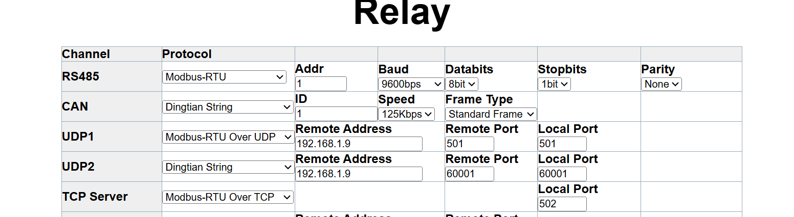
Than I configured the EW11, extract of my configuration backup :
<!--SYS Config-->
<SYS key='User' value='admin'>
<SYS key='Password' value='yourpwd'>
<SYS key='DHCP' value='Enable'>
<SYS key='Ip Address' value='10.10.100.10'>
<SYS key='GateWay' value='10.10.100.254'>
<SYS key='Mask' value='255.255.255.0'>
<SYS key='Host Name' value='dr-tom-ew11-rs485-wp-1'>
<SYS key='DNS' value='10.0.6.3'>
<SYS key='Telnet' value='Enable'>
<SYS key='Telnet Port' value='23'>
<SYS key='Echo' value='Enable'>
<SYS key='Web' value='Enable'>
<SYS key='Web Port' value='80'>
<SYS key='Ipv6' value='Disable'>
<SYS key='Ipv6 address' value=''>
<SYS key='Ipv6 DHCP' value='Disable'>
<SYS key='NTP' value='Enable'>
<SYS key='NTP Server' value='0.be.pool.ntp.org'>
<SYS key='NTP Port' value='123'>
<SYS key='NTP GMT' value='2'>
<SYS key='Customer ID' value='EW11'>
<SYS key='Config Version' value='0'>
<SYS key='NetworkMode' value='Router'>
<SYS key='WiFiMode' value='STA'>
<SYS key='WiFiAPSSID' value='EW11_E52C'>
<SYS key='WiFiAPKey' value=''>
<SYS key='WiFiSTASSID' value='yourwifisssid'>
<SYS key='WiFiSTAKey' value='yourwifipwd'>
<SYS key='WiFiAPCH' value='0'>
<SYS key='WiFiHideSSID' value='0'>
<SYS key='WiFiRoamingEn' value='0'>
<SYS key='ScanRSSIThreshold' value='0'>
<SYS key='ConnectRSSIThreshold' value='0'>
<SYS key='LanIpAddress' value='10.10.100.254'>
<SYS key='LanMarsk' value='255.255.255.0'>
<SYS key='LanDhcpEn' value='Enable'>
<SYS key='EthernetMode' value='WAN'>
<SYS key='Longitude' value='0.000000'>
<SYS key='Latitude' value='0.000000'>
<SYS key='SmartConfig' value='SmartLink'>
<SYS key='ModbusTime' value='0'>

<!--UART Config-->
<UART key='Baudrate' value='115200'>
<UART key='Databits' value='8'>
<UART key='Stopbits' value='1'>
<UART key='Parity' value='NONE'>
<UART key='FlowCtrl' value='Disable'>
<UART key='Software FlowCtrl' value='Disable'>
<UART key='Xon' value='11'>
<UART key='Xoff' value='13'>
<UART key='Protocol' value='Modbus'>
<UART key='Frame Length' value='16'>
<UART key='Frame Time' value='100'>
<UART key='Tag Enable' value='Disable'>
<UART key='Tag Head' value='00'>
<UART key='Tag Tail' value='00'>
<UART key='Buffer Size' value='512'>
<UART key='gapTime Size' value='50'>
<UART key='cliGetin' value='1'>
<UART key='serialStr' value='+++'>
<UART key='waitTime' value='300'>

<!--SOCK Config-->
<SOCK name='netp' key='Name' value='netp'>
<SOCK name='netp' key='Protocol' value='TCP-SERVER'>
<SOCK name='netp' key='Local Port' value='502'>
<SOCK name='netp' key='Buffer Size' value='512'>
<SOCK name='netp' key='KeepAlive' value='60'>
<SOCK name='netp' key='Timeout' value='0'>
<SOCK name='netp' key='Security' value='NONE'>
<SOCK name='netp' key='Connect Mode' value='Always'>
<SOCK name='netp' key='VcomEn' value='0'>
<SOCK name='netp' key='Rout' value='uart'>
<SOCK name='netp' key='maxAccept' value='3'>
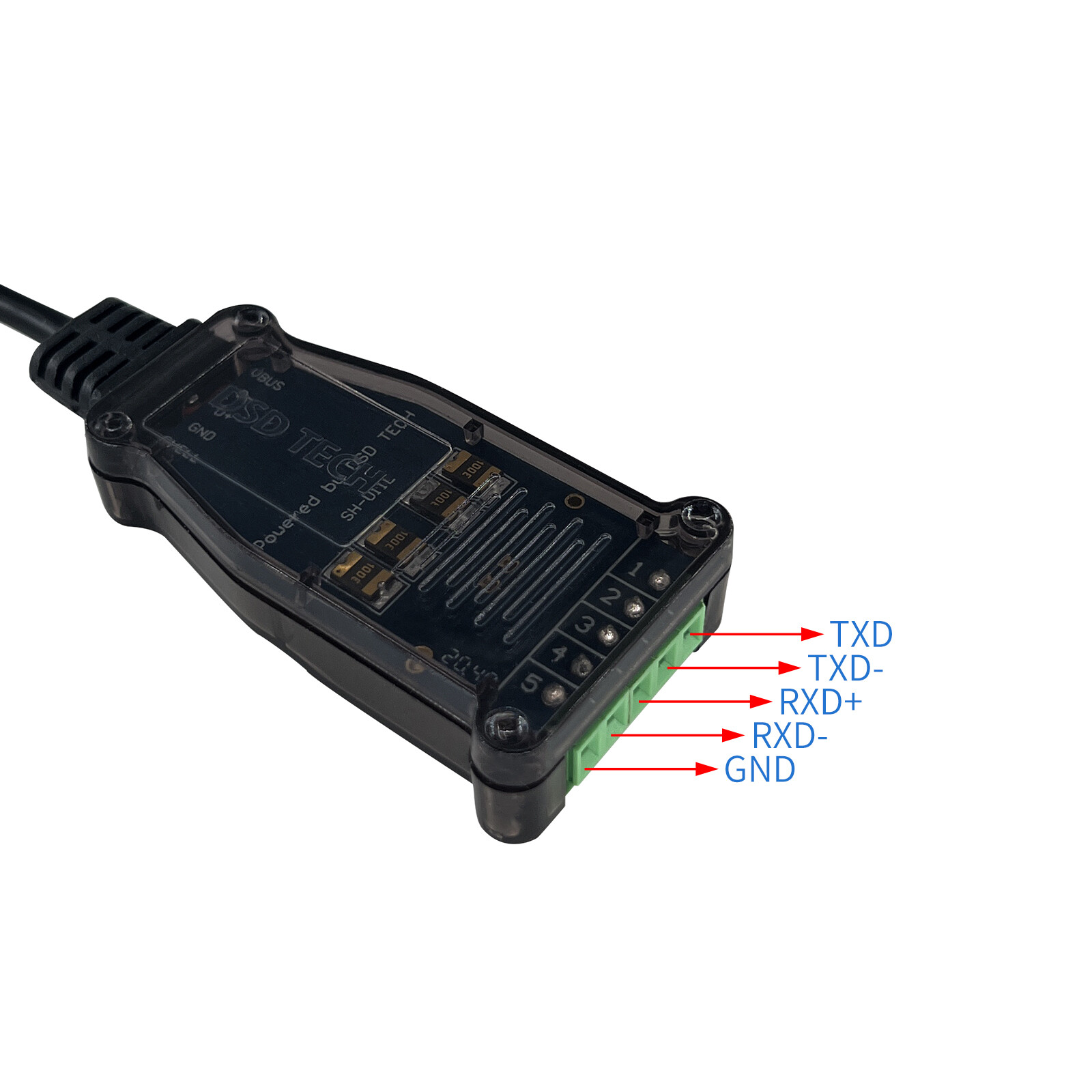
The sensor is connected to the EW11 in this way :
[u]Sensor        <------->    Elfin EW11[/u]   <------>   24V power supply
BLUE                           A
RED                            +                          +
GREEN                          -                          -
YELLOW                         B
Of course not everything worked from the first time ![]()
First I used a USB to RS485 converter and connected the probe to it.
By using a trial version of ModBusPoll I was able to connect to it (9600 baud, 8data, no parity, 1 stop bit, mode RTU) and read the registers.
Then I wrote (adapted) a python script that can read the 7 registers available over TCP via EW11.
#!/usr/bin/env python3

# TDV 11/02/2024 : sudo pip3 install pyModbusTCP

# function code | Data start address | Number of data | Data bytes | Data range | Command meaning
# --------------+--------------------+----------------+------------+------------+-----------------------------------------------------------
# 0x03          | 0x0000             | 1              | 2          | 1-255      | Read the slave machine address
# 0x03          | 0x0001             | 1              | 2          | 0 = 1200   | Baud rate reading
#                                                                  | 1 = 2400   |
#                                                                  | 2 = 4800   |
#                                                                  | 3 = 9600   |
#                                                                  | 4 = 19200  |
#                                                                  | 5 = 38400  |
#                                                                  | 6 = 57600  |
#                                                                  | 7 = 115200 |
# 0x03          | 0x0002             | 1              | 2          | 0 = unit no| Pressure unit
#                                                                  | 1 = CM     |
#                                                                  | 2 = MM     |
#                                                                  | 3 = MPa    |
#                                                                  | 4 = Pa     |
#                                                                  | 5 = KPa    |
#                                                                  | 6 = MA     |
# 0x03          | 0x0003             | 1              | 2          | 0 = ####   | Decimal places represent 0-3 decimal points respectively
#                                                                  | 1 = ###.#  |
#                                                                  | 2 = ##.##  |
#                                                                  | 3 = #.###  |
# 0x03          | 0x0004             | 1              | 2          |-32768-32767| Measure the output value
# 0x03          | 0x0005             | 1              | 2          |-32768-32767| Transmitter range zero
# 0x03          | 0x0006             | 1              | 2          |-32768-32767| Transmitter range is full point

""" Read 10 holding registers and print result on stdout. """

import time
from pyModbusTCP.client import ModbusClient


# init modbus client
c = ModbusClient(host='10.0.6.164', port=502, debug=True, auto_open=True)

# main read loop
while True:
    # read 7 registers at address 0, store result in regs list
    regs_l = c.read_holding_registers(0, 7)

    # if success display registers
    if regs_l:
        print('reg ad #0 to 7: %s' % regs_l)
    else:
        print('unable to read registers')

    # sleep 2s before next polling
    #time.sleep(2)
When that succeeded, I was able to eventually after reading and tweaking to do the HA integration. Using the elevated logging helped ![]()
# Logger config
logger:
  default: warning
  logs:
    homeassistant.components.modbus: debug
    pymodbus: debug
This gives us the following logging, once working. On every retrieval the sequence is augmented.
024-02-12 02:03:17.493 DEBUG (SyncWorker_11) [pymodbus.logging] Current transaction state - IDLE
2024-02-12 02:03:17.493 DEBUG (SyncWorker_11) [pymodbus.logging] Running transaction 1
2024-02-12 02:03:17.493 DEBUG (SyncWorker_11) [pymodbus.logging] SEND: 0x0 0x1 0x0 0x0 0x0 0x6 0x1 0x3 0x0 0x4 0x0 0x1
2024-02-12 02:03:17.493 DEBUG (SyncWorker_11) [pymodbus.logging] New Transaction state "SENDING"
2024-02-12 02:03:17.493 DEBUG (SyncWorker_11) [pymodbus.logging] Changing transaction state from "SENDING" to "WAITING FOR REPLY"
2024-02-12 02:03:17.606 DEBUG (SyncWorker_11) [pymodbus.logging] Changing transaction state from "WAITING FOR REPLY" to "PROCESSING REPLY"
2024-02-12 02:03:17.606 DEBUG (SyncWorker_11) [pymodbus.logging] RECV: 0x0 0x1 0x0 0x0 0x0 0x5 0x1 0x3 0x2 0x0 0x0
2024-02-12 02:03:17.606 DEBUG (SyncWorker_11) [pymodbus.logging] Processing: 0x0 0x1 0x0 0x0 0x0 0x5 0x1 0x3 0x2 0x0 0x0
2024-02-12 02:03:17.606 DEBUG (SyncWorker_11) [pymodbus.logging] Factory Response[ReadHoldingRegistersResponse': 3]
2024-02-12 02:03:17.606 DEBUG (SyncWorker_11) [pymodbus.logging] Adding transaction 1
2024-02-12 02:03:17.606 DEBUG (SyncWorker_11) [pymodbus.logging] Getting transaction 1
2024-02-12 02:03:17.606 DEBUG (SyncWorker_11) [pymodbus.logging] Changing transaction state from "PROCESSING REPLY" to "TRANSACTION_COMPLETE"
2024-02-12 02:03:21.996 DEBUG (SyncWorker_3) [pymodbus.logging] Current transaction state - TRANSACTION_COMPLETE
2024-02-12 02:03:21.996 DEBUG (SyncWorker_3) [pymodbus.logging] Running transaction 2
2024-02-12 02:03:21.996 DEBUG (SyncWorker_3) [pymodbus.logging] SEND: 0x0 0x2 0x0 0x0 0x0 0x6 0x1 0x3 0x0 0x4 0x0 0x1
2024-02-12 02:03:21.996 DEBUG (SyncWorker_3) [pymodbus.logging] New Transaction state "SENDING"
2024-02-12 02:03:21.996 DEBUG (SyncWorker_3) [pymodbus.logging] Changing transaction state from "SENDING" to "WAITING FOR REPLY"
2024-02-12 02:03:22.087 DEBUG (SyncWorker_3) [pymodbus.logging] Changing transaction state from "WAITING FOR REPLY" to "PROCESSING REPLY"
2024-02-12 02:03:22.087 DEBUG (SyncWorker_3) [pymodbus.logging] RECV: 0x0 0x2 0x0 0x0 0x0 0x5 0x1 0x3 0x2 0x0 0x0
2024-02-12 02:03:22.087 DEBUG (SyncWorker_3) [pymodbus.logging] Processing: 0x0 0x2 0x0 0x0 0x0 0x5 0x1 0x3 0x2 0x0 0x0
2024-02-12 02:03:22.087 DEBUG (SyncWorker_3) [pymodbus.logging] Factory Response[ReadHoldingRegistersResponse': 3]
2024-02-12 02:03:22.087 DEBUG (SyncWorker_3) [pymodbus.logging] Adding transaction 2
2024-02-12 02:03:22.087 DEBUG (SyncWorker_3) [pymodbus.logging] Getting transaction 2
2024-02-12 02:03:22.087 DEBUG (SyncWorker_3) [pymodbus.logging] Changing transaction state from "PROCESSING REPLY" to "TRANSACTION_COMPLETE"
2024-02-12 02:03:26.996 DEBUG (SyncWorker_11) [pymodbus.logging] Current transaction state - TRANSACTION_COMPLETE
2024-02-12 02:03:26.996 DEBUG (SyncWorker_11) [pymodbus.logging] Running transaction 3
2024-02-12 02:03:26.996 DEBUG (SyncWorker_11) [pymodbus.logging] SEND: 0x0 0x3 0x0 0x0 0x0 0x6 0x1 0x3 0x0 0x4 0x0 0x1
2024-02-12 02:03:26.996 DEBUG (SyncWorker_11) [pymodbus.logging] New Transaction state "SENDING"
2024-02-12 02:03:26.998 DEBUG (SyncWorker_11) [pymodbus.logging] Changing transaction state from "SENDING" to "WAITING FOR REPLY"
2024-02-12 02:03:27.083 DEBUG (SyncWorker_11) [pymodbus.logging] Changing transaction state from "WAITING FOR REPLY" to "PROCESSING REPLY"
2024-02-12 02:03:27.083 DEBUG (SyncWorker_11) [pymodbus.logging] RECV: 0x0 0x3 0x0 0x0 0x0 0x5 0x1 0x3 0x2 0x0 0x0
2024-02-12 02:03:27.083 DEBUG (SyncWorker_11) [pymodbus.logging] Processing: 0x0 0x3 0x0 0x0 0x0 0x5 0x1 0x3 0x2 0x0 0x0
2024-02-12 02:03:27.083 DEBUG (SyncWorker_11) [pymodbus.logging] Factory Response[ReadHoldingRegistersResponse': 3]
2024-02-12 02:03:27.083 DEBUG (SyncWorker_11) [pymodbus.logging] Adding transaction 3
2024-02-12 02:03:27.083 DEBUG (SyncWorker_11) [pymodbus.logging] Getting transaction 3
2024-02-12 02:03:27.083 DEBUG (SyncWorker_11) [pymodbus.logging] Changing transaction state from "PROCESSING REPLY" to "TRANSACTION_COMPLETE"
I hope this guide is helpfull for someone ![]()
When I get enough posts, I will add some screenshots.
Cheers,
Tom