Monitor for Sump Pump with Battery Backup

I made a sump pump monitor with an ESP32 development board and a submersible level (pressure) sensor. The idea behind this project was to meet several goals:

  • Locally controlled
  • Retains functionality without power or internet
  • No failure modes that can affect the sump pump’s operation
  • Tells me how often the pump is operating
  • Alerts me when either the primary or backup pump is not working
  • Alerts me when the backup battery is not charging or is drained

This monitor operates off the 12V battery that powers the backup sump pump. Here’s the major parts I used, plus miscellaneous wires, resistors, bypass capacitors, headers, DC barrel jacks, solder, etc. Some of the links are just examples; I got some items from AliExpress and others I had on-hand.

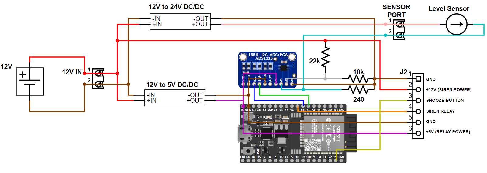
This is the schematic I came up with.

They make current-to-voltage converters which I could have used instead of creating the voltage divider circuit, but I didn’t see much point to that. I have no experience with this one, but here is an example if you want to use that option.

I connected it to the battery with a harness that goes from ring terminals to a DC plug, with an in-line fuse:

Doing this project made me realize how absolutely awful I am at soldering. Please don’t feel the need to tell me how bad I am, but I’ll take tips if you have them. The DC barrel jacks soldered to the board aren’t being used; this project went through several iterations and I reworked the board multiple times while I was still changing the schematic. Yes, even after I had it running on a breadboard and thought it was “good enough”. The one smart thing I did was to use headers instead of soldering the ESP32 and ADS1115 boards directly to the perfboard. It allowed easier access during soldering, I didn’t have to worry about overheating those components, and if I screw anything up they are easy to swap out.

This is all the components placed into the project box:

And here it is installed, sitting on the backup battery:

The level/pressure sensor sits in the bottom of the sump. It doesn’t really matter if it is vertical or laying horizontal, as long as it doesn’t interfere with any of the pumps. I have mine vertical, with the wire zip tied to some of the PVC pipe. You can’t see anything with both sump pumps in there, so here’s a picture with the sensor sitting in the sump while I was replacing the backup sump pump. The sensor is circled in red.

The code is quite complicated for all the sensors and monitoring I wanted to have. Here it is, feel free to modify as needed:

2 Likes

Very nice project!

Since the ADS115 gives you more ADC, is it worth adding additional level sensors for redundancy?

I wondered if the sensor clogs easily if there is lots of silt in the water. But maybe a cheesecloth or ultra fine wire mesh wrapped perforated PVC pipe to enclose the sensor solves that?

It’s certainly possible to add another level sensor, but I didn’t think it was necessary. I am using all the channels currently since I have 3 measurements (12V battery, 5V supply, and level sensor voltage) and they are all differential (measuring relative to the 4th channel which is ground). There shouldn’t be a difference since the ADS1115’s ground and the 4th channel ground should be at the same level, so I could probably change that and use the 4th channel for something else. But I think the level sensor going bad and unnoticed during a rain storm is a low probability. I could even add some logic to alert me if the pumpout interval was short and suddenly the pumpouts stop, or if the sump level doesn’t change for a long period of time. But I watch the level on my Lovelace dashboard so it’s not really a concern for me.

As to the sensor clogging, it’s just sensing pressure and there’s really no diaphragm movement, and therefore no flow in & out of the sensor. I’ve had it in there for about 6 months and there’s no buildup of anything to be worried about.

1 Like

I am almost finished the build…again thank you…however, still waiting for the level sensor and 12V siren from Aliexpress but I have encountered a couple of issues when testing that I am hoping you can help with. When hooking up the relay, without the alarm showing activated on the dashboard, the moment the siren relay wire (i.e. orange/4 in your diagram) is attached, the relay clicks and allows 12 volts to pass through and thus, I assume the siren would be going off. I have the output on NO and COM. Additionally, when I press the physical alarm pause button, the dashboard does indicate it’s active but it doesn’t cause the relay to switch the 12V/siren off. I believe that only when the alarm is on should it pass through the 12Vs while the pause button should open the relay and stop the siren. I have rechecked the wiring many times but clearly I have got something wrong. Any thoughts? From a dashboard perspective, everything seems to be displaying fine (obviously, only getting 0 for any measurement readings related to the level sensor) so I am a bit lost at the moment.

The snooze will only silence the warnings, and not the critical faults. If you don’t have the 12V battery connected, then the low battery voltage fault should be active and the siren should be on. So it may be working as designed.

If you didn’t remove it, the code will have the esp32 host a web server. You can visit that IP address with a browser and see which faults are active:

Sump Pump Fault: Backup Pump Not Operating	  OFF	
Sump Pump Fault: Battery Not Charging	      OFF	
Sump Pump Fault: Critically Low Battery	      OFF	
Sump Pump Fault: Primary Pump Not Operating	  OFF

If the “Backup Pump Not Operating” or the “Critically Low Battery” faults are ON, then the alarm will be enabled regardless of snooze status.

Ah so good to know that the snooze only silences the warnings, but that said, if the primary pump is not operating, for example, are you saying that there would be no way to shut off the siren while addressing that issue? For my test, I am using a 12v power supply (versus a battery) to power the unit (supplying a constant 12.089V - sump pump 12v battery voltage and 4.9V - sump pump 5v supply voltage respectively) and all faults are “off” including the “sump pump alarm sounding”. Would the fact that I don’t have the level sensor installed yet have anything to do with it? Is there any logic to the code I can check and/or build in so when I connect the wire to the relay it stays “open” until a fault or a warning occurs?

FYI - I was able to simulate a battery not charging fault while providing enough power to ensure the esp32 continued provide all the available stats with 5V continuing to be supplied to the relay. In this case, connecting the siren wire to the relay did nothing which I found interesting. Based on this, it would appear I may have something flipped as one would expect that at full constant input power of 12V, the siren wire would not be activating the relay. And sorry, in your coding, I found the comment where you indicate that with faults, it is not possible to snooze them.

SOLVED: Based on the findings above, I set the output pin 25 in your code to…Inverted: false (versus true). Now when I drop the voltage, the relay activates and provides power to the siren.

Good to hear you solved it. As to your question about snoozing: The snooze silences the primary pump fault and the battery not charging fault. The other two faults (backup pump fault and battery dead fault) are not snoozable. I did this because I didn’t want to have a scenario where, for example, the primary pump fails, and so I snooze it (so I can fix it later) but then the backup pump fails but that is snoozed as well. And then my basement floods.

That makes perfect sense, thanks for clarifying. I do wonder, however, in the case where the battery is no longer charging, at what voltage will it be when the 12v siren just stops. When I was testing, I recall being somewhere below 10v (need to test again to be sure), when the esp32 disconnected from HA and the relay began fluttering. I would assume the siren, which requires 12v would konk out sooner. Once I have the final pieces (level sensor and siren) to complete the build, I will do some further testing but with what it can provide when the battery is working properly, I am really impressed with what you have done.

I’d expect it’ll be different depending on what hardware you’re using. For me, I set it at 10.8V because that is the voltage that my backup pump is supposed to stop working. I’m hoping both the siren and the ESP still work at that voltage, but I haven’t tested either yet. It’s on my to-do list… :slight_smile:

I have received all the remaining parts and everything is working properly on the test bench. Again, a huge thanks to you for all your instructions, pictures and clarifications along the way. It’s been a great learning experience. That said, my very last question (ok maybe :slight_smile: ) is that I noticed that in one of the pics, you have a capacitor across in the incoming power terminals. I assume this is the bypass capacitor you mentioned but it is not in your circuit diagram. Perhaps a total noob question but is it required in this application and if so, what is the correct size?

I was having issues with noise in my level sensor signal, so I started putting bypass capacitors on a few different components. If your signals aren’t noisy then I wouldn’t worry about it. I put these on before I changed to the 12-to-5V converter (previously I was using an automotive 12V-to-USB converter and powering the nodeMCU through its USB port). I suspect the USB adapter I was using was the source of the noise, but I had made several changes before I noticed the noise issue was solved so I can’t be sure. I think I used a 100nf but I’m not sure, I just used the biggest one I had.

Glad to hear it’s working, post a picture when you get it installed in its final resting place!

edit: here’s what the noisy level sensor data looked like originally:
image