For a long time I’ve been searching for a “perfect” light relay to use in my home.
A perfect light relay for me should satisfy the following requirements:
- It must be controlled locally with a normal on/off switch.
- It must be controllable from Home Assistant locally without any sort of clouds with their state accurately represented in HA.
- It should be easy to integrate in my house.
I live in a flat with traditional for ex-USSR light wiring - there is only live wire exposed at the switch and both live and neutral wires in the lamp. The rest of the wiring is hidden in concrete. Another limitation for me is - all my top lights’ switches are located at ceiling with a rope coming down from it.
My first try at this problem was a Wemos D1 mini with a relay module. I’ve constructed that thing from off-the-shelf part from AliExpress and some local stores.

This solution worked for me for some time, but it was bulky and required power wiring to all switches, which is quite sub-optimal, as I needed to run a wire from ceiling (where my old switch was) and from power outlet to the new switch location on the wall, which are located quite apart in my flat, which resulted in 2-3 meters of exposed power cable. It goes without saying, that this solution was not scalable beyond 1 or 2 instances. So it failed miserably on “easy to integrate with home” requirement.
Next I’ve looked at several no-neutral solutions. Some of them required strange wiring, or even overheating capacitors. Some of them were designed to be put inside an existing wall plates, which do not exist in my house and would require quite a bit of drilling in concrete to create. Given all these disadvantages, I shied away from them.
Next I’ve discovered RF 433MHz buttons and relays. Together with an RF-WiFi hub, they could be easily integrated, I thought. I’ve even bought Sonooff WiFi-RF433 bridge, that were converted by the community to Tasmota and Esphome with varying effort. I had some success with it too, replacing ESP8266’s firmware to Esphome. Although it burned successfully, I was greeted with the effort of teaching the system new buttons and switches. While researching this topic, I came about a wireless relay with kinetic wireless switches.
I’ve ordered this kit from LoRaTap in hope to use it with my converted wifi-rf hub after seeing reviews of a similar products [1][2] by the russian electronics youbuter “Electronics in lens”.
This relay is somewhat “dumb” - it has no WiFi connectivity.
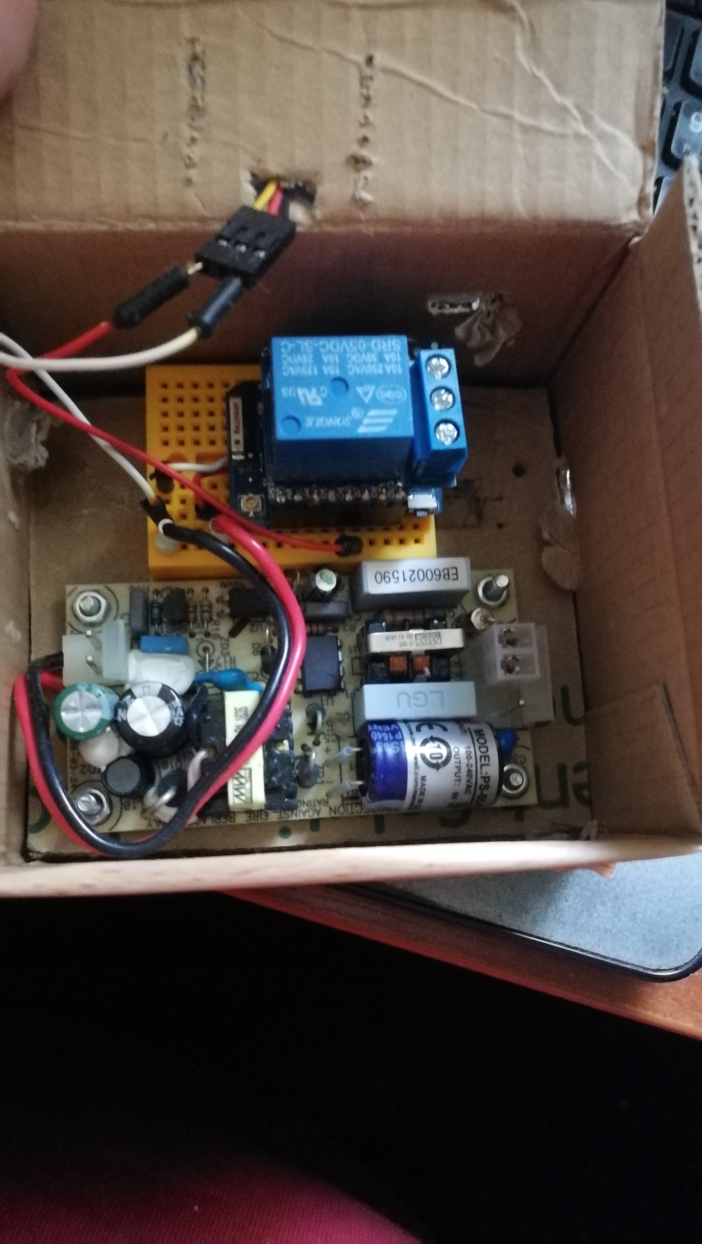
Having received the relay, the first thing I’ve done was openning up its plastic hull. Inside, there is a board with a relay and a MCU board. It is the same as the one from this post by @graffitiwriter on RR300WST relay minus the blue WiFi circuit board.
I’ve run around the board with a testing probe, trying to understand the connections of things inside. I was interested in the two main components: the button and the onboard LED. From that post, I’ve got that the board had 3.3v supply for the MCU.

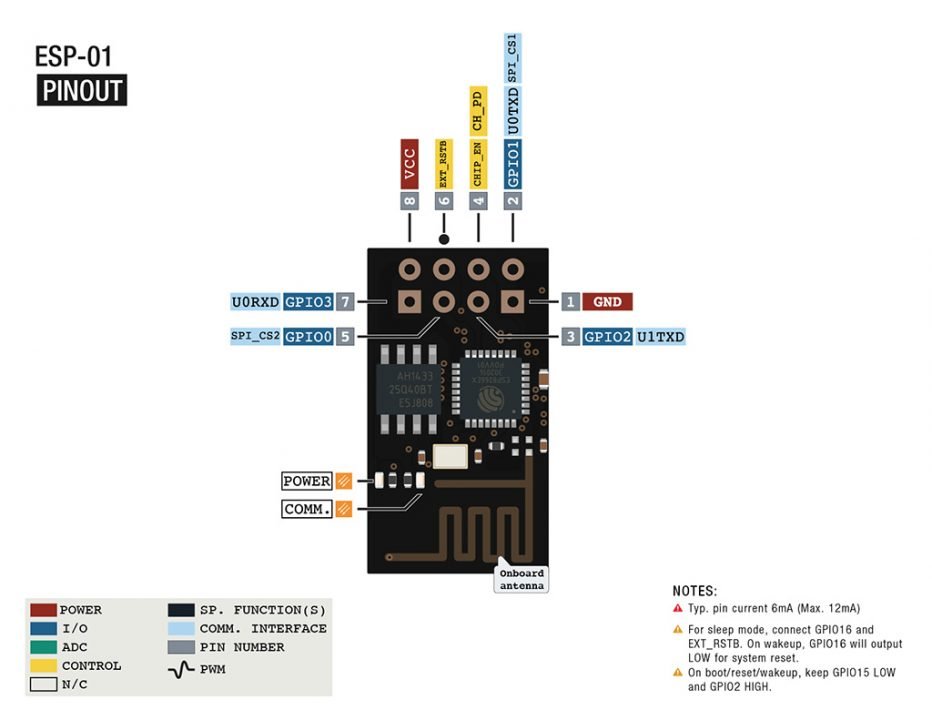
As I fugured out both button and LED signal, I could hook up an ESP8266 to it. I had a ESP01_1M module lying around my home, with three 10K resistors needed to boot and run it. For details, see pinout alongside with this guide with wiring diagramm. I’ve ignored buttons to reset and GPIO0, as they wouldn’t be used in the device. For programming, I short GPIO0 to ground while plugging the device into USB via USB-UART transceiver. The first and the hardest challenge is getting first minimal Esphome firmware on the thing. Then it could be reprogrammed over-the-air (OTA).
The relay has 3 modes of button interaction:
- “Normal” operation - once clicked, it toggles the relay.
- “Learn” mode - the button should be held for at least 5 seconds. Once entered, the LED should begin flashing. When learn mode is entered, you should click the wireless switch two times for the relay to register and remember it. After successful registration, it goes back to “Normal” mode.
- “Reset” mode - the button should be held for at least 15 seconds. Once entered, the LED should begin flashing fast. When the button is released, the device goes back to “Normal” mode.
The wiring from the relay to ESP01 is very straightforward (as labeled in the picture):
| Relay | ESP01 |
|---|---|
| 3.3v | 3.3v |
| GND | GND |
| Button | GPIO3 |
| LED | GPIO1 |
Here is my config for the ESP8266 with all three modes accessible. I’ve commented some values, which you should supply to make it work in your network.
esphome:
  name: # some name for your node
  platform: ESP8266
  board: esp01_1m

wifi:
  ssid: # your ssid
  password:  # your wifi password

# Enable logging
logger:
  hardware_uart: UART0_SWAP

# Enable Home Assistant API
api:
  password: # your api password

ota:
  password: # your ota password

binary_sensor:
  - platform: gpio
    pin:
      number: GPIO1
      inverted: true
    internal: true
    id: led
    on_state:
      then:
        if:
          condition:
            lambda: return not id(mode_switch_blocker).state;
          then:
            light.control:
              id: # main_light
              state: !lambda |-
                return x;

output:
  - platform: gpio
    pin:
      number: GPIO3
      inverted: true
    id: button

  - platform: template
    id: led_button_combined
    type: binary
    write_action:
    - if:
        condition:
          lambda: return state != id(led).state and not id(mode_switch_blocker).state;
        then:
          - output.turn_on: button
          - delay: 100ms
          - output.turn_off: button

light:
  - platform: binary
    name: # "This name would be shown in HA ui"
    output: led_button_combined
    id: # main_light

switch:
  - platform: template
    id: mode_switch_blocker
  - platform: template
    name: # This is the learn mode switch
    id: learn_mode
    turn_on_action:
      - switch.template.publish:
          id: mode_switch_blocker
          state: on
      - output.turn_on: button
      - delay: 5.5s
      - output.turn_off: button
      - switch.template.publish:
          id: mode_switch_blocker
          state: off
      - switch.turn_off: learn_mode

  - platform: template
    name: # This is the reset mode switch
    id: reset_mode
    turn_on_action:
      - switch.template.publish:
          id: mode_switch_blocker
          state: on
      - output.turn_on: button
      - delay: 20s
      - output.turn_off: button
      - delay: 1s
      - switch.template.publish:
          id: mode_switch_blocker
          state: off
      - switch.turn_off: reset_mode

I think, I’ve found my perfect light relay:
- It is controlled locally with a normal on/off switch which is wireless on top of everything.
- It is controllable from Home Assistant locally through ESP01 with real state pulled from relay’s led.
- It is easy to install this thing on the ceiling inside lamp’s cover, while shorting the previous switch and installing the wireless switch in any required place.
It should be noted, that ESP01 is not the only module that could be used with this relay. I consider the current setup quite hacky. I’ve designed a board with ESP-07 to be used in this switch to make the overall setup a bit less hacky. And I’ll later design a hull to attach the board to, which could be 3D printed.
I’m open to discussion and constructive criticism.