This project was inspired by Installing Smart Whole House Fan (QuietCool) - Share your Projects! - Home Assistant Community, and still a little bit ongoing, but most of the major stuff is done.
Ehh, as a new user I can only have one embeded media, so have had to remove most of pictures.
I have a new construction, and got an ugly and dumb quietcool fan pre-installed with ugly dumb control, where one has to program binary logic gates via switch.
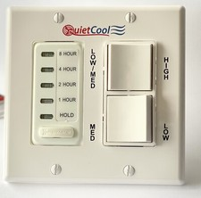
They offer a little bit better options now, with some wifi+app, but I wanted something more native to home-assistant, and reliable wall control (if home assistant goes down).
The original project (in the first paragraph), that inspired me, have had only two modes for the fan - High and Low. My fan have had three modes, so I have had to be more creative.
I was thinking of using Shelly Pro 3, and doing some custom programming, however the “secret feature” of QuietCool fans, is that the motor may die, if more than one line (High/Medium/Low) would be simultaneously energized. I was afraid that something might get screwed up, or being reset, and the motor dies. I needed some hardware protection, like in that article above, and I found it - by using relays(one can read more about relays on Wiki).
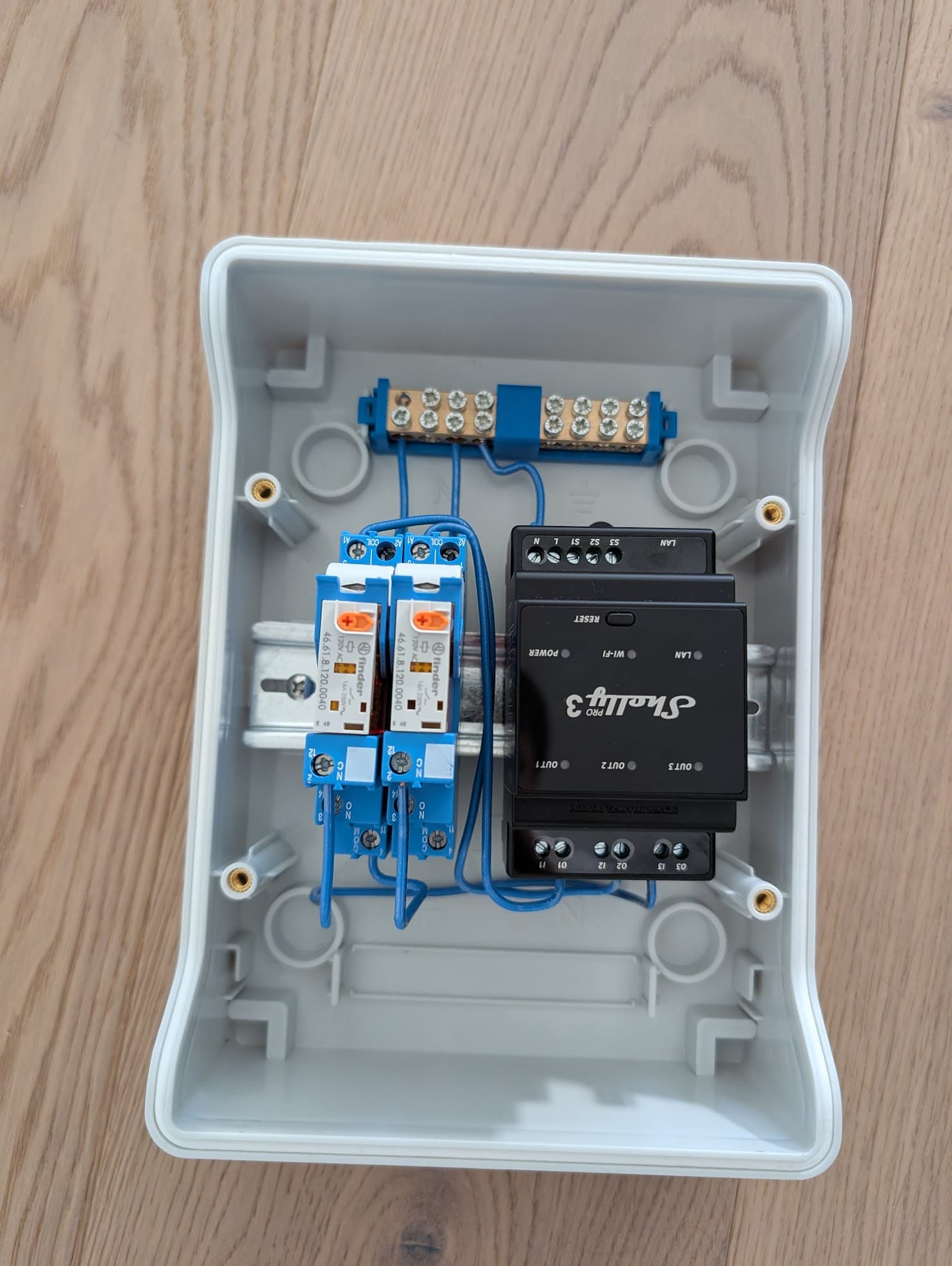
It was my first somewhat serious project: I ordered Shelly Pro 3, ordered two SPDT relays (I used 4C.02.8.120.0060SPA AC relay):
Also I needed DIN rail mount box, and matter-based replacements for the ugly QuietCool switches:
I went with Leviton Scene Controller, to be used as timer, and with MOES Matter-WiFi 3 Gang Light Switches for the physical 3-button matter switch, to control the speed of fan, even if HomeAssistant is down.
Once I removed the wall box, there have been 3 cables coming in:
- Line/Neutral/Ground from the breaker
- Line/Neutral/Ground to the motor
- 3 wires to energize with Line voltage(at most one must be energized), to select High, Medium or Low speed (connected to that ugly two-button switch).
Behind the wall, was the small mechanical room, and that’s where I was going to install my small DIN-rail breaker panel.
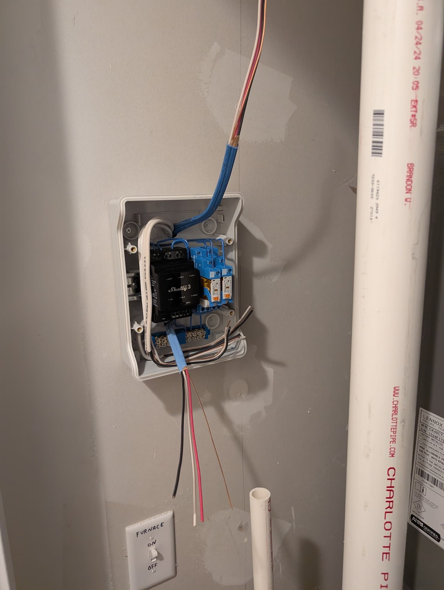
View from inside the mechanical room - three top cables, are the same three original cables, pulled form the gang box to mechanical room:
And I run two more cables (the bottom), from this new box, to the old switch:
Blue one - is a “traveller” one, to be connect Shelly’s S1/S2/S3 with 3-button switch, and the white one, is standard romex to provide power to smart switches.
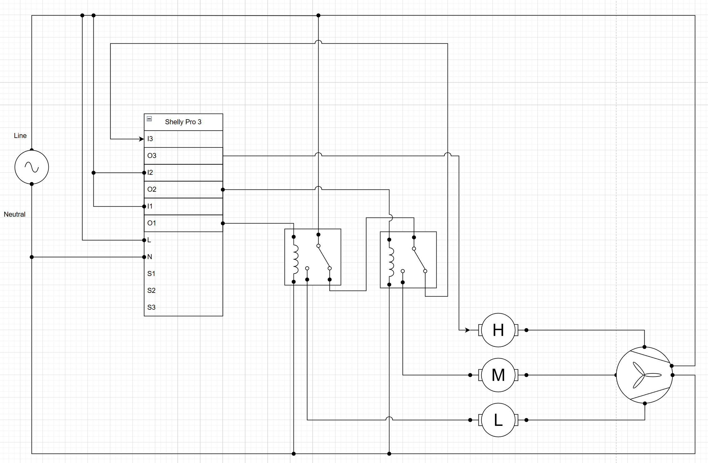
Here’s the total wiring diagram (all the ground wires are omitted from this grand scheme)
(S1/S2/S3 connected to smart physical switch not shown).
Relays prevent simultaneous energizing of more than one motor line.
If I1/S1 is on - then fan runs on low speed, no matter what do the other switches say. If I1/S1 is off, but I2/S2 is on, then fan runs on medium speed, no matter what I3/S3 says. If 1&2 are off, but I3/S3 is on, then fan runs on maximum speed.
I wired everything this way, since mostly fan is used on maximum speed, and this wiring wouldn’t activate the relays, and save them.
What’s left?
Do actual programming of Leviton Scene controller as a timer.
Do some automation:
- if inside is warmer than desired temperature, and outside is cooler than desired temperature, and doors/windows are open for 3+ minutes - turn off the AC and activate the fan on maximum speed.
- if doors/windows are closed - open the vent outdoor damper, turn off the AC, and start running on low speed.