ATTENTION:
-
This guide is only for the original Reolink Doorbell. “V2” devices appear to use a 900MHz instead of 433MHz frequency to communicate with their chime, which is incompatible. If anyone knows of similar programmable “900MHz” smart devices, please post a link so I can add it to the guide.
-
The required MHCOZY device listed and linked below varies sometimes by the Amazon seller. The other versions appears to be a non-ESP based board, and/or a different input voltage requirement (i.e. not compatible with Tasmota or the upgraded doorbell transformer). Please use caution when ordering, as the other devices listed will most likely not work with this guide without performing an ESP module transplant, and/or providing an alternate power source. I’ve provided some alternate Aliexpress links that appear to be the right type of board if the recommended Amazon unit is unavailable.
After lots of searching on how to get my Reolink Video Doorbell to work with my original electro/mechanical chime, I finally found/figured out a standalone Cloud/WiFi/HA free solution using a 433MHz WiFi board flashed with Tasmota. This is still a work-in-progress (for example there is currently a 1 - 2 second delay from pressing the button, to the relay actually cycling), so minor changes or tweaks may be implemented. FYI, I need to go back through and take more pictures, so those will be added soon!
Before we begin, the standard WARNINGS/CAUTIONS:
WARNING – SHOCK HAZARD: Although we will only be dealing with “low-voltage,” it is still AC voltage we’ll be working with. As such there is always the risk of electrical shock. While this is very mild for the majority of people, it can still be:
- slightly to mildly painful
- cause injury or damage from sudden reflex
- cause damage to equipment (i.e. miswiring/short damage)
- cause more serious injury to those susceptible (i.e. medical conditions, etc.)
Furthermore, if working on or at the doorbell transformer itself there is risk to exposure to the 120VAC Mains, which can cause serious injury or death. Always shut off circuit breakers, lockout/tagout (optional, but recommended – google for more information), and VERIFY power removal with either a voltage probe or DMM. If you’re unfamiliar with this equipment and their usage, STOP! Get a professional to do it for you!
WARNING – BURN HAZARD: Unless using a flashing jig, there will be some soldering involved. Typical soldering temperatures are in the 600°- 650°F range, and will instantly burn your skin if you slip or handle it wrong. Furthermore, you can easily damage equipment from using too high of a heat setting, or from again slipping and touching an unintended component.
CAUTION – CUT INJURY/DAMAGE: You’ll be using standard hand tools, which can be sharp (e.g. wire strippers). Slipping or misuse can obviously lead to you cutting yourself, so use caution. Furthermore, you can always damage the components we’ll be working with, which adds time and cost to the project. Slow and steady DIYers… there’s no prize for finishing this the fastest!
So now that those are out of the way, let’s list what we need:
-
Reolink Video Doorbell (obviously)
-
Upgraded doorbell transformer (needed for video doorbells either way)
-
MHCOZY DC 7-32V 433MHz Relay WiFi module
(Amazon seller varies this item sometimes. Verify it’s the “7-32V with 433Mhz RF” option, and that the board pictured is the same as one pictured below BEFORE purchasing)
Aliexpress Alternate 1 - select 7-32V 433MHZ Shell (case included)
Aliexpress Alternate 2 - select DC5-32V 433MHZ case (case included)
Aliexpress Alternate 3 - select 7-32V and 433 remote (no case)
(It’s Aliexpress, so it’s a bit of a dice roll sometimes whether what you see is what you get.
Recommend using PayPal or another buyer protection option if available!) -
Soldering iron or a PSF-B01 Jig
-
Solder and flux (soldering method only)
-
Fine single strand 30AWG or finer wire (soldering method only)
-
DMM and/or Voltage Probe
-
Standard Hand Tools
(Except for the MHCOZY, all links are just examples of what you need)
Now on to the steps…
Step 1) Disassemble the MHCOZY DC 7-32V 433MHz Relay WiFi module.
The plastic case has no screws, but does have 2 small tabs on both long sides, so you’ll need to gently pry this apart to remove the bottom cover. You can use a small prying tool, flat head screw driver, scribe, etc. to accomplish this. Once apart, verify the WiFi module is a PSF-B01 or other ESP based board. If it’s not, then this method will not work without Cloud/WiFi/HA support. It may be possible to transplant an ESP-12F or 12S module, but that exceeds the scope of this guide at this time.


Step 2) Flash the latest version of Tasmota onto the module.
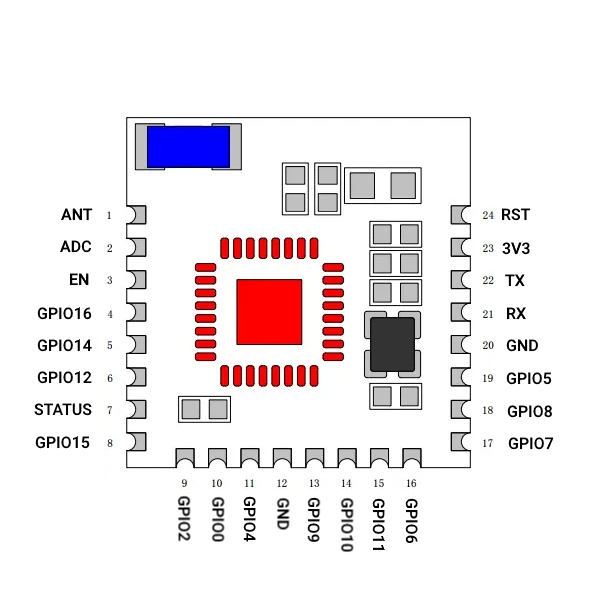
There are tons of how-to guides and YouTube videos on this, so I’m not going to get into the nitty gritty here. Basically this is where the soldering/jig and USB TTL Serial Flasher come in. Personally I just soldered mine, but the jig makes it pretty easy if you want to go that route (especially if you have your own 3D printer). I’ll list the PSF-B01 pinout, but again just search here or on YouTube for videos to do this if you’re unfamiliar. I will add that the button on the MHCOZY does connect GPIO0 to Ground, so you can use that to get the module into flashing mode. Since I already wrote it below for another member, flashing in a nutshell:
- connect your USB serial TTL flashing device to your PC, and install the drivers if Windows doesn’t do this automatically the first time you plug it in (it’s been a while, but I think this was the correct driver for windows), afterwards disconnect the USB from the device;
- Download Tasmotizer. Yes you can technically use a web browser for flashing Tasmota these days, but I still prefer this app… just seems to work far smoother for me;
- connect your flashing device to the PSF-B01 board (either by soldering or using the above jig) VCC to 3V3, GND to GND, TX to RX, and RX to TX;
- press and hold the MHCOZY button, then plug in your flashing device to the USB port on your PC. Hold for about 3-5 seconds, then release the button. This puts the ESP chip into flashing mode;
- open Tasmotizer and flash your device (again lots of YouTube videos for using this). I generally recommend backing up, erasing, and then programming Tasmota to the chip.
- after you confirm Tasmota flashed to the chip properly, go ahead and remove your leads from the MHCOZY.
Step 3) Temporarily power things up.
Prior to installing the Reolink Video Doorbell or MHCOZY in their permanent locations, we need to pair things up. This is best done on a work table where we can power the two up next to each other. First, power up your Reolink Video Doorbell. Depending on the model you have, this can be done by either plugging in a POE ethernet cable (POE version obviously), or by hooking up the 24VDC adapter that comes with the WiFi version. Give the Reolink some time to bootup (about 30 seconds). Next plug in a powered USB mini cable to the MHCOZY, and open the Tasmota web browser associated with this device (see aforementioned guides/YouTube videos). We’ll setup Tasmota proper in a bit, but in the meantime verify that clicking the “Toggle” button with the default Tasmota settings (i.e. Sonoff Basic) on the browser actually toggles our relay.


Step 4) Program the 433MHz signal.
The Reolink Video Doorbell transmits a 433MHz signal to its included plugin chime. The MHCOZY board we have can be programmed easily to this signal. First press and hold the button on the MHCOZY for 3 seconds until the blue LED illuminates. Now immediately press the Reolink Doorbell button, and you should see the red LED come on, as well as hear the relay “click” after a few seconds. If you don’t, wait until the Reolink’s blue swirling light stops, and try pressing the doorbell button again. If you don’t see the red LED come on, or hear the relay switch, then repeat the steps from the MHCOZY 3 second button hold step. Continue on once pressing the doorbell button toggles the MHCOZY.

Step 5) Setting up Tasmota for proper doorbell chiming.
Here we’re going to setup Tasmota on the MHCOZY to work properly with our chime when it’s triggered. From the same Tasmota web browser we opened up above, perform the following:
-
Click Configure, Configure Other
-
In the Template box copy the following:

{“NAME”:“MHCOZY RF 1CH”,“GPIO”:[32,0,0,0,0,0,0,0,224,320,0,0,0,0],“FLAG”:0,“BASE”:18}
-
Check the Activate box, name the “Device Name” and “Friendly Device Name 1” whatever you want (short and simple is best), and click the green Save button at the bottom. The device will reboot at this point, which usually takes about 20 – 30 seconds, and will take you back to the Main Menu. “MHCOZY RF 1CH” should now be displayed at the top of the page, along with whatever you named your device directly under it. If not, check that you properly entered the template info which includes the { } symbols, and that you checked the checkbox.
-
Click Console
-
Enter the following:


so73 1
pulsetime 3
rule1 on button1#state do event chime endon
rule2 on event#chime do backlog rule1 0; power1 1; ruletimer1 10 endon on rules#timer=1 do rule1 1 endon
rule1 1
rule2 1
In addition to the normally single toggling of the MHCOZY, the Reolink transmits its 433MHz signal for ~3 seconds or so, which won’t produce a useable chime for the majority of people. Furthermore, the toggle signal is inconsistent, and sometimes toggles 2 or even 3 times per doorbell button press. The options and rules we just implemented resolve these issues into a nice, quick, and single toggle of our original doorbell chime. Quick note on the “pulsetime” command, the 3 represents 300ms / 0.3 seconds. You can set this to whatever you personally need/want for your doorbell chime, with each whole number representing 100ms / 0.1 seconds. I just felt 300ms produced a “normal” on/off time for my chime.
Step 6) Disconnect everything, and prepare for long-term install.
Here’s where everybody’s method is going to differ a bit. First go ahead and disconnect our temporary setup. You may reassemble the MHCOZY back into its case at this time if you plan on using/keeping it. The MHCOZY board is capable of running on multiple power types, to include the same power supply that powers your Reolink Doorbell and original chime. This guide will show the wiring for that method, but you can use whatever method you wish provided everything is powered, and your chime only receives transformer output 1 from the MHCOZY Relay NO (Normally Open) Port. As for this method, with the circuit breaker off to the doorbell transformer and properly verified (and preferably locked out/tagged out), you need to connect everything together using your existing 18AWG wire and/or additional wire from our parts list, as demonstrated in this lovely diagram for the WiFi variant:

While you could utilize the MHCOZY board’s input terminals instead of the wire nuts and pigtails, I personally don’t recommend that. It’s just a lot to try and cram into those simple and small terminals, and it’s just better to use pigtails and wire nuts or wire levers (for you fancy pants outs there). Also if you’re using the POE Reolink variant, then you skip the pigtails that are going to the Reolink in the diagram. Just make sure that your wiring does the following:
-
Doorbell transformer output 1 goes to MHCOZY Input 1, MHCOZY Relay COM Port, and Reolink Video Doorbell Input 1 (WiFi Version Only)
-
Doorbell transformer output 2 goes to Chime TRAN, MHCOZY Input 2, and Reolink Video Doorbell Input 2 (WiFi Version Only)
-
MHCOZY NO Relay Port goes to Chime FRONT
Once everything is wired as described, restore power to the doorbell transformer, and give a minute or so for everything to bootup. At this point give your Reolink Video Doorbell a try. Personally I’d have someone standing by at the breaker box (or wherever the shutoff is for your doorbell transformer) just in case something goes haywire or unexpected. Provided you’re using a beefy transformer, like a 24VAC 40VA or the likes, everything should work as expected.
Please note: This guide was made to be newbie friendly. Yes I could have made some things in Tasmota more advance, especially on the Console Commands… I just wanted to keep things simple. Also like I stated at the beginning, this is very much a work-in-progress, and I’m still tinkering with other boards. I have definitely found some that respond faster, but either they lacked an ESP based WiFi module, or they implemented the 433MHz learning in the original non-ESP board… which made them reliant on the Cloud, WiFi, or HA… which I didn’t want. A doorbell “chime” should be independent from those things working. So aside from commenting on those aspects, please feel free to make suggestions! ![]()
 ), however, as you pointed out these rule conditions aren’t available in the standard Tasmota binary. Like I said at the end of my guide I wanted to keep things as newb friendly as possible, and lets face it we know we would lose people attempting this DIY if compiling a custom binary was involved!