Before I over complicate this process, I want to check with the community to see if I’m over complicating the process ;).
A double throw double pole rocker switch is designed to easily switch power from one destination to the next from the same power source.
To modify a standard switch so the polarity is reversed, I would connect the ON leads together, criss crossing them so they’re reversed. Then, instead of ON/OFF/ON, the switch would be UP/OFF/DOWN or NORMAL/OFF/REVERSED.
To simulate this with relays so it’s all done digitally through HA, I could take two relays, feed one relay’s center connector with 12V+ and the other with 12V-, then connect the leads to the actuators and program the relays to switch back and forth.
The one piece that is missing is the OFF. If the relays don’t have a neutral position between the normally on and normally off position, and they don’t fire together exactly in sync, then I imagine I would create a short, blow a fuse in the 12V power supply and/or not blow a fuse and cause a fire.
The only thing I can think of is to place a third relay on one of the leads from the power supply, then program a routine to ensure that the power is cut before the polarity is changed.
Am I on the right track or is there a better way to do this?
I had made this for someone else but I think you’ll get the idea. Power the second relay from the N/C contact on the first relay. The first relay has to be off for the second to operate.
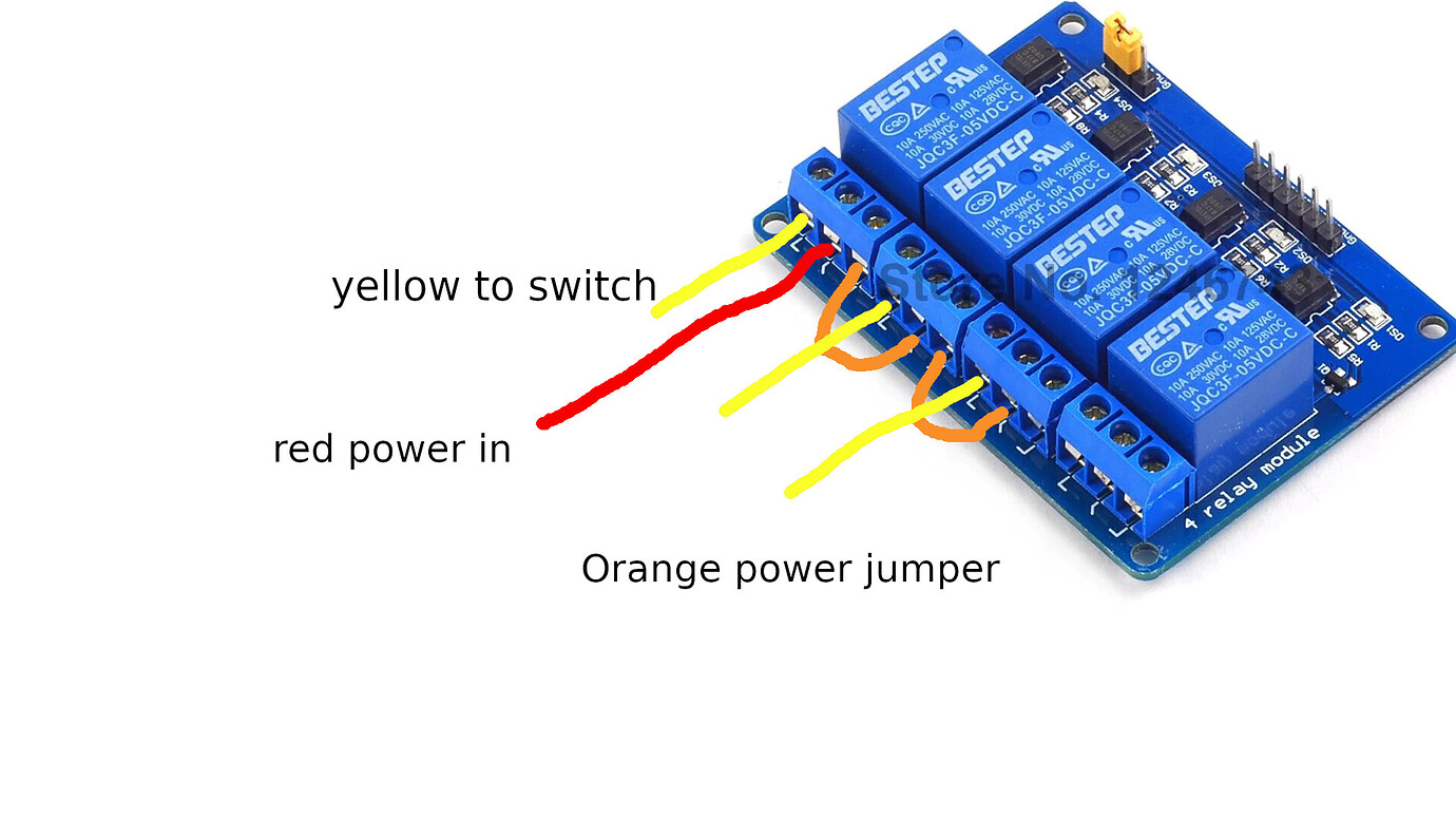
Sorry as I said it was for something else. Hopefully this will make more sense. The positive (red) relay 4 and negative (black) relay 1, comes in on the common terminal.
The orange jumpers from relay 4 feed one side of relays 2 and 3.
The grey/white jumpers from relay 1 to the other side of relay 2 and 3.
The yellow lines are the motor output connected to the common of relay 2 and 3.
This way power can only be on one side of the motor at a time.
You are on the right track with your relay logic but to ensure you don’t short it out during switching you can use a double pole (or more) relay. The ones shown in the posts above are only single pole which is why the examples use multiple relays. Get yourself a relay with more sets of contacts and you only need one… however, again as you mention, you wont have an ‘off’ position so using a second relay will give you the option to cut power completely.
The double pole would be nice because one relay would switch both connections mechanically reducing the risk of shorting. Is there a double pole that can be used with ESPHome (Wemos D1 Mini or ESP8266, etc?)
3 relays with a crossover connection. First image would be NC and circuit would be controlled by 3rd relay. Disable circuit, then switch 1 and 2 to the open position to reverse the flow.
Ok state 1 if you toggle relay 2 you will short to ground. If you want to do 3 relays you can do it like this.
All relays off = off (both motor legs to negative)
Relay 2 on = direction 1
Relay 1 & 3 on = direction 2
Any other combination will also be an off position. all on, 1&2 on, 2&3 on
I saw your other post, I’d connect them both to this one setup and use a rheostat on the faster motor. It doesn’t matter what side of the load it’s on. It’s something you’d set once.
True, if I toggle relay 2 I would short to ground, but, using NodeRED, I could program the logic to ensure that the timing is sufficient to ensure that relay 3 has opened the circuit to allow time for 1 and 2 to switch…but I do see the risk.
So, in your diagram, you have 12v+ connected to NC on relay 1 which energizes the 2nd relay’s open pin, so that means that relay 2 would need to be activated, while 1 and 3 remain de-activated. Then, to reverse polarity, I would have to activate relay 1 to send 12v+ to relay 3, and also activate relay 3 to complete the 12v+ delivery to the 12v- motor lead, and deactivate relay 2 to switch to the ground. (do I have it, or am I backwards?)
Then, if relay 1 were activated inadvertently, it would send 12v+ to a dead end at relay 3. Or if relay 2 were inadvertently deactivated, we would just have all 12v- connected to the motor with no complete circuit. I think I see…no matter what, if the relays are out of position, the worst that could happen is a dead end 12v+ or a 12v- loop of nothing.
So if the microcontroller lost power and the relays were all dead, but the 12v power supply continued to chug along, there would be no short and it would be safe.
Regarding the rheostat, wouldn’t there be a potential of one of the actuators slowing down over time due to possible failure, or something of that nature? I suppose I would just re-adjust it.
What would be really cool is if I could measure the load on the actuators, use those sensors to calculate a digital adjustment to a digital speed control, and auto-calibrate (more work than it’s worth, but kinda cool.)
You would only be able to have a negative loop not a positive one. If you used 4 relays there would be a completely disconnected position available. That’s just for future reference. I’ve used a 4 relay setup for 220v gate operators in the past.
As for the rheostat it should be just a real slight adjustment, maybe would need readjustment. If it was more complicated like a curve then the on the fly adjustable would be great. Curve being a spot where the motor struggles more than at other points.
Fusion360 doesn’t seem to have orange ;). Lol…well, yellow it is. So this is the setup now per your diagram. I’ve already ordered the 4 relay module since I’ll also be adding an LED strip that the 4th relay can turn on and off.
The DC Motor Speed control that I have causes a short and kills the ATX power supply if the polarity is reversed. This happens if the speed control is connected between the relay and the motor. The only way I can get the speed control to work is to ensure that the input polarity on the speed control is never changed, thus, it needs to come before the relay power input, in which case, it will affect both motors on the 3-Relay setup.
So, I went with 5 relays. 2 Pairs of relays, each pair imitating a DPDT relay with the risk of shorting. To avert the risk, I added a 5th relay to kill the power completely between the power supply and the speed control, then setup NodeRED with logic that ensures power is off before the 4 relays are switched to reverse the polarity.
The worst that could happen is the ATX Power Supply will be tripped (as it has some sort of failover protection) and that would only happen if the 5th, or shall we call it, the 1st relay in the chain were to fail.
Either way, It’s working, and working well…and I’m only dealing with 12V, so it’s not a nuclear situation. ;).
This is the likely culprit. A rheostat (potentiometer) used in series with the motor supply is just a resistor. You would interrupt one line to the motor connecting to the center and 1 end pin of the rheostat. Your just creating a choke point in the power supply.
Hi @arretx ,
Were you able to finish your project? I was searching for something similar to use 3 bistable solenoids with a 4ch relay module.
Unfortunately these solenoid need an inverted polarity to turn off. At first I tought they would work with a normal signal input to either turn off and on.
So I was searching for a solution to reverse this 9v DC
I was able to finish it. I ended up using 4 relays. One of the relays kills the power to the others so there’s no risk of shorting the connection, then I created a flow in NodeRED to manage the switching for the desk’s up/down functions.