I recently finished a sump pump monitoring project using ESPHome and Home Assistant, and wanted to share the setup and lessons learned in case it helps others designing something similar.
Goals
I wanted a solution that:
- Tells me where the water level is, not just “dry” or “already flooded”
- Complements my Aqara leak sensor
- Counts how many times the pump actually drains
- Uses simple, reliable, waterproof hardware
Hardware
- Wemos D1 Mini
- 2 LEDs
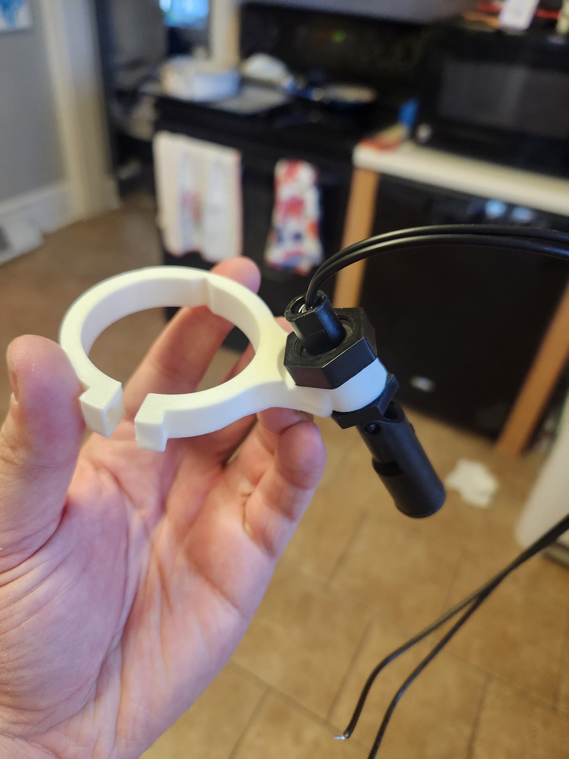
- Lower float: mounted just below the pump’s normal trigger point
- Upper float: mounted well above normal high water as an overflow warning
- Floats mounted to the discharge pipe using 3D-printed brackets and zip ties
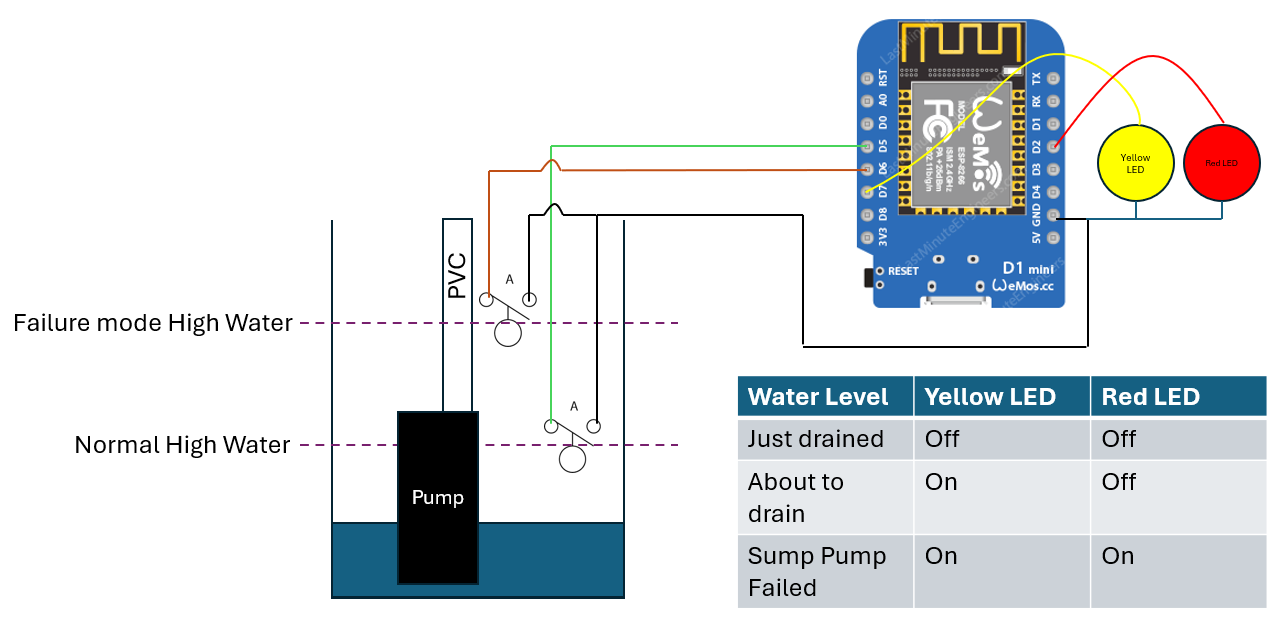
- Simple wiring:
GPIO → float → GND(INPUT_PULLUP)
Wiring:
Home Assistant
Dashboard Design
![]() Drained – both floats OFF
Drained – both floats OFF
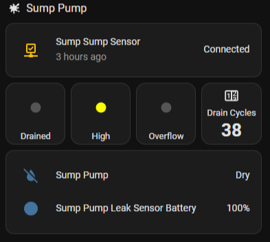
![]() High – lower float ON
High – lower float ON
![]() Overflow – upper float ON
Overflow – upper float ON
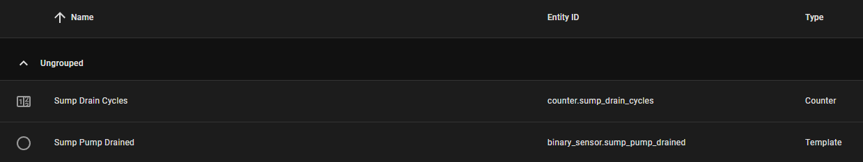
![]() Drain Cycles – counter with double-tap reset
Drain Cycles – counter with double-tap reset
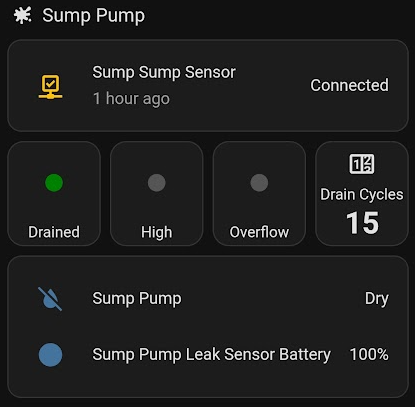
Derived “Drained” State (Green Indicator)
To get a clean “pump just ran / pit is empty” indicator, I added a Template Binary Sensor helper via the UI:
{{ is_state('binary_sensor.sump_pump_sump_rising', 'off')
and is_state('binary_sensor.sump_pump_sump_overflow_risk', 'off') }}
ON → pit drained (green)
OFF → water at or above a float
Esphome config:
captive_portal:
output:
  - platform: gpio
    id: yellow_led
    pin: GPIO13   # D7

  - platform: gpio
    id: red_led
    pin: GPIO4

  - platform: gpio
    id: green_led
    pin: GPIO5    # D1

binary_sensor:
  - platform: gpio
    name: "Sump Rising"
    id: sump_rising
    pin:
      number: GPIO14 #D5
      mode: INPUT_PULLUP
      inverted: false
    filters:
      - delayed_on: 200ms
      - delayed_off: 500ms
    on_press:
      - output.turn_on: yellow_led
    on_release:
      - output.turn_off: yellow_led

  - platform: gpio
    name: "Sump Overflow Risk"
    id: sump_overflow
    pin:
      number: GPIO12 #D6
      mode: INPUT_PULLUP
      inverted: false
    filters:
      - delayed_on: 200ms
      - delayed_off: 500ms
    on_press:
      - output.turn_on: red_led
    on_release:
      - output.turn_off: red_led

  - platform: status
    name: "Sump Pump Online"
Helpers
Drained Template:
{{ is_state('binary_sensor.sump_pump_sump_rising', 'off')
   and is_state('binary_sensor.sump_pump_sump_overflow_risk', 'off') }}
Automations
#Increments the counter every time the lower sensor is on (closed).
alias: Sump pump-  Increment drain cycles
description: ""
triggers:
  - entity_id:
      - binary_sensor.sump_pump_sump_rising
    to:
      - "off"
    trigger: state
    from:
      - "on"
actions:
  - action: counter.increment
    data: {}
    target:
      entity_id: counter.sump_drain_cycles
mode: single
#High water phone notification
alias: Sump Pump – High Water Alert
mode: single
trigger:
  - platform: state
    entity_id: binary_sensor.sump_pump_sump_rising
    to: "on"
    for: "00:00:10"
action:
  - service: notify.mobile_app_xxxxx_s_s22
    data:
      title: "Sump Pump Alert"
      message: "Water reached the high-water float. Check the sump pit."
      data:
        priority: high
        ttl: 0
This setup has gives me more confidence in the sump system than a single “water detected” sensor does.
If you have any ideas on how to improve it or questions, feel free to ask any questions.