Teltonika (OpenWRT / RutOS) custom GSM modem modbus

This post is a quickly written guide that might help some other users and also an invitation for questions.

My home internet is via mobile ISP, and I recently upgraded to a Teltonika RUTX50 dual SIM card router. This replaced my older RUT950 router, and both of these Teltonika units run a modified version of OpenWRT called RutOS… so the following guide should work on most SIM routers capable of running OpenWRT, albeit with tweaks.

The issue: I lock my router to a fixed GSM band in order to prevent tower/cell hopping, to make my connection more stable. However, my ISP seems to power-down or switch off cells/towers overnight – I assume to conserve energy – and combined with my band lock this creates connection drop-outs.

So, to determine exactly what is happening, I want to log detailed info from my router’s GSM modem into Home Assistant: The primary serving band, secondary & additional bands, a record of band switching as forced by my ISP, and all subsequent RSSI, RSRP, RSRQ, SINR values per band.

OpenWRT/Teltonika by default does not pass this info to Modbus, but is here is how you can get it…

ROUTER SETUP

  1. Follow these instructions re: Custom Modbus Register Block…

https://wiki.teltonika-networks.com/view/Modbus_custom_register_block_RutOS

  1. SSH or Router UI > System > CLI and create the following script…
$ vi /bin/extramodbus
#! /bin/ash
while true
do
gsmctl -CA 'AT+QCAINFO' -o --modemtime 2 | tr '\n\r,\"' ',' > /tmp/regfile
echo '0000000000 0000000000 0000000000 0000000000 0000000000 0000000000 0000000000 0000000000 0000000000 0000000000' >> /tmp/regfile
sleep 8
done
  1. Save the script and make it executable…
$ chmod +x /bin/extramodbus
  1. An explanation of the above script…

4a) Use the GSMCTL command to get a bunch of info from the modem. More info about GSMCTL can be found here: https://wiki.teltonika-networks.com/view/AT_Commands

gsmctl -CA 'AT+QCAINFO' -o --modemtime 2

4b) Use the tr command to reformat the response of the gsmctl into comma delimited values…

| tr '\n\r,\"' ','

4c) Write this info to a file called /tmp/regfile

> /tmp/regfile

4d) Pad out the /tmp/regfile … If a Modbus server is given data file that contains less than the expected number of characters / below the register count, it returns an error and fails. We want the /tmp/regfile to contain a minimum of 250 characters (aka a register count of 125, = 250 characters / 2) so running the echo command below appends 100x '0’s to the end of the /tmp/regfile. Hacky but it works, and I would love to know a cleaner solution…

echo '0000000000 0000000000 0000000000 0000000000 0000000000 0000000000 0000000000 0000000000 0000000000 0000000000' >> /tmp/regfile

EDIT: An alternative to adding zeros could be to replace the echo line with the following printf line instead…

printf "%250s" "#END#" >> /tmp/regfile

… where “%250s” = ‘add a string of 250 null characters’ followed by the string ‘#END#’ just to make life easier for humans :slight_smile: … your choice, echo or printf… Ideally I’d use the truncate command but this is not installed with embedded Linux on our routers.

4e) Run the script every 8 seconds…

sleep 8
done
  1. SSH or Router UI > System > Custom Scripts and tell the script file to run in the background, start on boot etc.
extramodbus &
exit 0
  1. If everything is working then /tmp/regfile should look something like this:
76543210,+QCAINFO: ,PCC,,1300,111,,LTE BAND 3,,1,222,-90,-11,-56,6,,+QCAINFO: ,SCC,,103,333,,LTE BAND 1,,1,444,-95,-10,-77,9,0,-,-,,+QCAINFO: ,SCC,,154570,1,,NR5G BAND 28,,555,,,vodafone EU,23/04/18,23:50:22,0000000000 0000000000 0000000000 0000000000 0000000000 0000000000 0000000000 0000000000 0000000000 0000000000
  1. From the Router UI, navigate to the following pages and copy the attached screenshots…

7a) Services > Modbus TCP Slave

7b) Services > Modbus TCP Master > Modbus TCP Slave Devices > Add / Slave Device Configuration

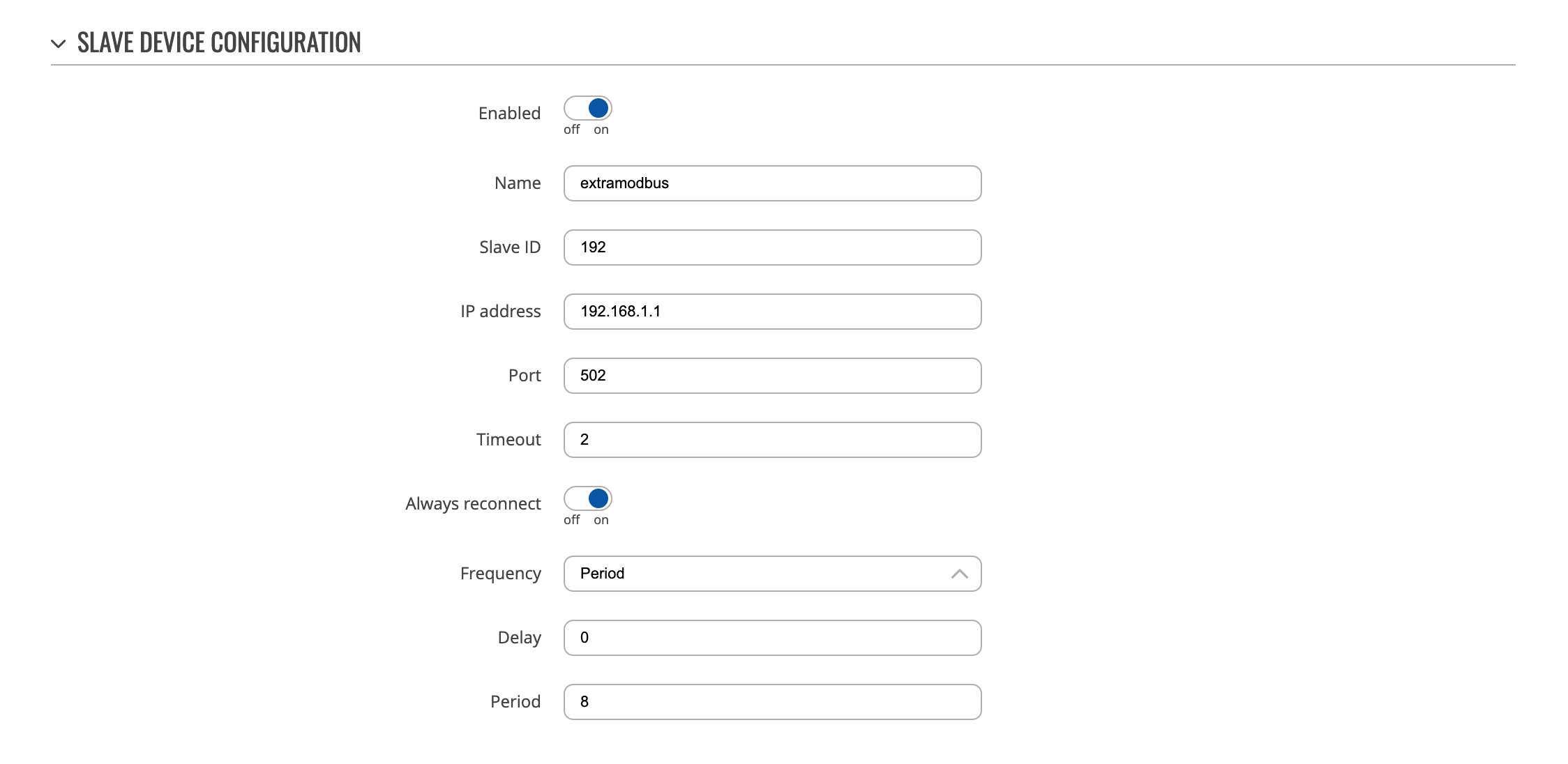
7c) Services > Modbus TCP Master > Modbus TCP Slave Devices > Edit (pencil icon) > Requests Configuration

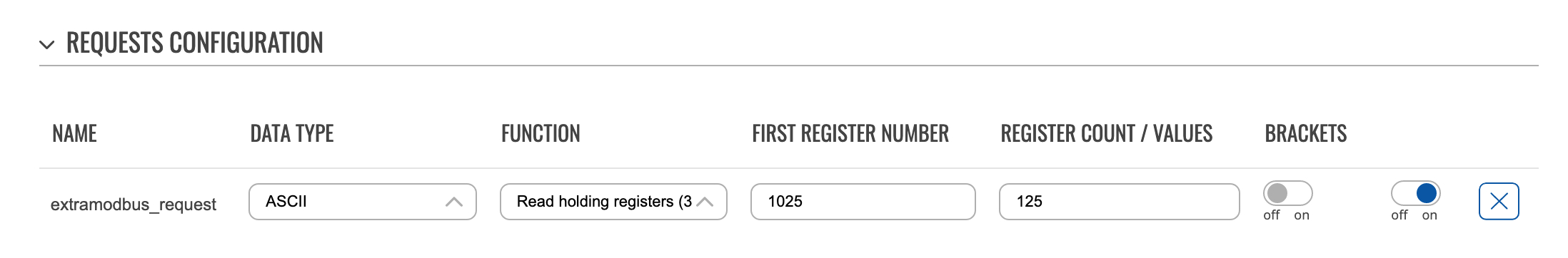
7d) Services > Modbus TCP Master > Modbus TCP Slave Devices > Edit (pencil icon) > Requests Configuration Testing > Test … pressing Test should return the contents of /tmp/regfile truncated to 125 registers aka 250 characters. If there are errors here, most likely the script we created above is not running (try rebooting the router to launch the script).

HOME ASSISTANT SETUP

I’ll skip explanations and just refer to the required YAML. Any questions just ask. Watch YAML indentation as per usual.

  1. configuration.yaml…
modbus: !include modbus.yaml
template: !include templates.yaml
  1. modbus.yaml…
### 'RUTX: Mobile Signal Strength' and 'RUTX: System Temp' are simply to check 
### if Home Assistant is receiving the standard Teltonika modbus messages.

  - name: TeltonikaRutOS
    type: tcp
    host: 192.168.1.1
    port: 502
    sensors:
      - name: "RUTX: Mobile Signal Strength" #aka sensor.rutx_mobile_signal_strength
        scan_interval: 30
        unit_of_measurement: "dBm"
        device_class: signal_strength
        slave: 192
        address: 4
      - name: "RUTX: System Temp" #aka sensor.rutx_system_temp
        scan_interval: 30
        unit_of_measurement: "°C"
        device_class: temperature
        slave: 192
        address: 6
      - name: "RUTX: ExtraModBus" #aka sensor.rutx_extramodbus aka /tmp/regfile
        scan_interval: 8
        slave: 192
        address: 1024 #I have no idea why the router creates register 1025, but Home Assistant needs 1024
        data_type: string
        count: 125
  1. templates.yaml… the .split(,)[n] function in the YAML splits the incoming modbus text based on comma counts. You may need to fiddle with these [n] numbers depending on the contents of your individual /tmp/regfile…
### This yaml will parse comma delimited ASCII modbus from 
### slave 192, address 1024 aka sensor.rutx_extramodbus aka /tmp/regfile

  - sensors:
      extramodbus_gsm_cell_id:
        friendly_name: "GSM Cell ID"
        value_template: "{{ states('sensor.rutx_extramodbus').split(',')[0] | int }}"
# GSM primary band
      extramodbus_gsm_band:
        friendly_name: "GSM Band"
        value_template: "{{ states('sensor.rutx_extramodbus').split(',')[7] }}"
      extramodbus_gsm_band_rsrq:
        friendly_name: "GSM Band RSRQ"
        value_template: "{{ states('sensor.rutx_extramodbus').split(',')[11] | float(0) }}"
        unit_of_measurement: "dBm"
        device_class: signal_strength
      extramodbus_gsm_band_rsrp:
        friendly_name: "GSM Band RSRP"
        value_template: "{{ states('sensor.rutx_extramodbus').split(',')[12] | float(0) }}"
        unit_of_measurement: "dBm"
        device_class: signal_strength        
      extramodbus_gsm_band_rssi:
        friendly_name: "GSM Band RSSI"
        value_template: "{{ states('sensor.rutx_extramodbus').split(',')[13] | float(0) }}"
        unit_of_measurement: "dBm"
        device_class: signal_strength
      extramodbus_gsm_band_sinr:
        friendly_name: "GSM Band SINR"
        value_template: "{{ states('sensor.rutx_extramodbus').split(',')[14] | float(0) }}"
        unit_of_measurement: "dBm"
        device_class: signal_strength
# GSM secondary band2
      extramodbus_gsm_band2:
        friendly_name: "GSM Band2"
        value_template: "{{ states('sensor.rutx_extramodbus').split(',')[22] }}" 
      extramodbus_gsm_band2_rsrq:
        friendly_name: "GSM Band2 RSRQ"
        value_template: "{{ states('sensor.rutx_extramodbus').split(',')[26] | float(0) }}"
        unit_of_measurement: "dBm"
        device_class: signal_strength
      extramodbus_gsm_band2_rsrp:
        friendly_name: "GSM Band2 RSRP"
        value_template: "{{ states('sensor.rutx_extramodbus').split(',')[27] | float(0) }}"
        unit_of_measurement: "dBm"
        device_class: signal_strength
      extramodbus_gsm_band2_rssi:
        friendly_name: "GSM Band2 RSSI"
        value_template: "{{ states('sensor.rutx_extramodbus').split(',')[28] | float(0) }}"
        unit_of_measurement: "dBm"
        device_class: signal_strength
      extramodbus_gsm_band2_sinr:
        friendly_name: "GSM Band2 SINR"
        value_template: "{{ states('sensor.rutx_extramodbus').split(',')[29] | float(0) }}"
        unit_of_measurement: "dBm"
        device_class: signal_strength
# GSM secondary band3
      extramodbus_gsm_band3:
        friendly_name: "GSM Band3"
        value_template: "{{ states('sensor.rutx_extramodbus').split(',')[40] }}"
      extramodbus_gsm_band3_rsrq:
        friendly_name: "GSM Band3 RSRQ"
        value_template: "{{ states('sensor.rutx_extramodbus').split(',')[44] | float(0) }}"
        unit_of_measurement: "dBm"
        device_class: signal_strength
      extramodbus_gsm_band3_rsrp:
        friendly_name: "GSM Band3 RSRP"
        value_template: "{{ states('sensor.rutx_extramodbus').split(',')[45] | float(0) }}"
        unit_of_measurement: "dBm"
        device_class: signal_strength
      extramodbus_gsm_band3_rssi:
        friendly_name: "GSM Band3 RSSI"
        value_template: "{{ states('sensor.rutx_extramodbus').split(',')[46] | float(0) }}"
        unit_of_measurement: "dBm"
        device_class: signal_strength
      extramodbus_gsm_band3_sinr:
        friendly_name: "GSM Band3 SINR"
        value_template: "{{ states('sensor.rutx_extramodbus').split(',')[47] | float(0) }}"
        unit_of_measurement: "dBm"
        device_class: signal_strength
# GSM secondary band4
      extramodbus_gsm_band4:
        friendly_name: "GSM Band4"
        value_template: "{{ states('sensor.rutx_extramodbus').split(',')[58] }}"
      extramodbus_gsm_band4_rsrq:
        friendly_name: "GSM Band4 RSRQ"
        value_template: "{{ states('sensor.rutx_extramodbus').split(',')[62] | float(0) }}"
        unit_of_measurement: "dBm"
        device_class: signal_strength
      extramodbus_gsm_band4_rsrp:
        friendly_name: "GSM Band4 RSRP"
        value_template: "{{ states('sensor.rutx_extramodbus').split(',')[63] | float(0) }}"
        unit_of_measurement: "dBm"
        device_class: signal_strength
      extramodbus_gsm_band4_rssi:
        friendly_name: "GSM Band4 RSSI"
        value_template: "{{ states('sensor.rutx_extramodbus').split(',')[64] | float(0) }}"
        unit_of_measurement: "dBm"
        device_class: signal_strength
      extramodbus_gsm_band4_sinr:
        friendly_name: "GSM Band4 SINR"
        value_template: "{{ states('sensor.rutx_extramodbus').split(',')[65] | float(0) }}"
        unit_of_measurement: "dBm"
        device_class: signal_strength
  1. And there you have it! Make up some nice HA sensors, automation triggers, whatever you want… the screenshot at the top of the post shows a 96 hour log of my ISP switching cells & bands on me, and a history graph of primary band signal stats.

Hopefully this helps someone. Cheers, Dan

p.s: thanks to Teltonika forum member Daumantas for the detailed explanation of GSMCTL.

3 Likes

This is great! It is just what I have been looking for! If you don’t mind to come back to you if I run into some question marks!

My first hurdle already is that I don’t seem be able to connect the SSH terminal via RMS. Anyway many thanks for this already!

edit:
Again thank you for this guide and I have got it working. I will take it as a reference for some other data which I like to pull off the router. On my list are data downloaded and uploaded this month. And I would like to add a reboot script to HA…

The data I have now raises already some question marks.
The cell ID I don’t fully understand. Does that mean that I am constantly connected to a different tower or to a different band?
I have copied your example of 4 GSM bands . The 4th one is always ‘empty’. The thing I don’t understand is which band is driving my router? The primary band? Can I influence that?

Thanks! Hit me up here with any questions. If the guide is not clear, let me know which points and I’ll rewrite it.

I’m not an expert at all, but managed to get it working nonetheless :slight_smile:

Your Qs:

The cell ID I don’t fully understand. Does that mean that I am constantly
connected to a different tower or to a different band?

EDIT: A mobile phone tower will usually have multiple cells (aka multiple antennas), each set to a specific band (aka broadcasting frequency) however your ISP can/might connect to your router using multiple bands (carrier aggregation?) to allow more bandwidth. The router shows this on page Router UI > Status > Network > Mobile > Data Transmission, as Carrier Aggregation & Connected Band.

This website might help explain your local situation: https://www.cellmapper.net

I have copied your example of 4 GSM bands . The 4th one is always ‘empty’.

Yeah, same here… I usually only have 3 serving bands from my closest cell tower, unless I set my router to default (Router UI > Network > Mobile > General > Band Selection > Auto) so that cells and bands are dictated by the ISP, and then sometimes I’ll be connected to a more distant cell tower with 4 or more bands.

In your case it’s possible your ISP only communicates over 3 bands within at your location. Or perhaps your router is only setup to communicate over 4G/LTE in which case you will not see any of the 5G bands?

The thing I don’t understand is which band is driving my router? The primary band?

One cell providing one band ostensibly drives your router, however the communication with your ISP is shared / split between all reachable cells & bands (aka carrier aggregation). I think simple signal metrics determines which is the ‘primary’ cell / band, but in reality it’s not one single cell / band driving your router. At least from what I understand?!

Can I influence that?

Yes to a point. On Teltonika routers you can Router UI > Network > Mobile > General > Band Selection > Manual (default is Auto) and then specify which bands you prefer. If your ISP provides, say, 4 bands locally but you notice that Band 1 happens to be the most reliable, then you can manually lock to Band 1. Note that you cannot choose bands that your ISP does not broadcast! Nor can you (at least from the router UI) lock to a specific cell tower. You can only lock to bands.

I think that’s it?! lol

Great and big thanks. Since the insight in cell-id’s and bands my interest and questions are growing just to improve the performance of my router. I have band 3 consistently on 5G but that band doesnt have any RSRP, RSRQ and SINR at all, which I believe is normal. However of the other bands incl signal strength the RSPR is excellent but RSRQ and SINR are poor and I wonder how I can improve that since my antenna is aimed straight at the cell tower with excellent signal strength (-47dBM).

One more observation. My system temperature comes out at 460-520C which is I think a factor 10 too high. Do you have the same?

Further more I have tried to extend the info with data sent and data received but these figures dont make sense either. This is the yaml:

### 'RUTX: Mobile Signal Strength' and 'RUTX: System Temp' are simply to check 
### if Home Assistant is receiving the standard Teltonika modbus messages.

  - name: TeltonikaRutOS
    type: tcp
    host: 192.168.1.1
    port: 502
    sensors:
      - name: "RUTX: Mobile Signal Strength" #aka sensor.rutx_mobile_signal_strength
        scan_interval: 30
        unit_of_measurement: "dBm"
        device_class: signal_strength
        slave: 1
        address: 4
      - name: "RUTX: System Temp" #aka sensor.rutx_system_temp
        scan_interval: 30
        unit_of_measurement: "°C"
        device_class: temperature
        data_type: int32
        slave: 1
        address: 6
      - name: "RUTX: Data uploaded this month" 
        scan_interval: 30
        unit_of_measurement: "Gb"
        data_type: int32       
#        device_class: temperature
        slave: 1
        address: 196 
      - name: "RUTX: Data downloaded this month" 
        scan_interval: 30
        unit_of_measurement: "Gb"
        data_type: int32
#        device_class: temperature
        slave: 1
        address: 194                
      - name: "RUTX: ExtraModBus" #aka sensor.rutx_extramodbus aka /tmp/regfile
        scan_interval: 10
        slave: 1
        address: 1024 #I have no idea why the router creates register 1025, but Home Assistant needs 1024
        data_type: string
        count: 125

You have any observations?

Regarding signal strength and picking the ‘best’ bands etc. etc .there are two other modem commands which you might want to try from the router command line / CLI:

gsmctl -A 'AT+QENG="SERVINGCELL"'

Which shows the current serving cell info, and returns data such as this…

+QENG: "servingcell","NOCONN"
+QENG: "LTE","FDD",999,01,987654,381,6300,20,3,3,2C9,-85,-12,-55,0,6,0,-
+QENG: "NR5G-NSA",999,01,381,-73,8,-12,154570,28,1,255

An explanation of which can mostly be figured out from this page: https://wiki.teltonika-networks.com/view/AT_Commands … but if anything is still a mystery just ask.

And then this other command show neighbouring cell info (aka cells that are in range of the router but currently not assigned as the primary band). This can be helpful in picking a cell / band that might have, say, worse RSSI that your primary serving cell but could have a much better SINR.

gsmctl -A 'AT+QENG="NEIGHBOURCELL"'

With typical results as so…

+QENG: "neighbourcell intra","LTE",6300,381,-13,-85,-53,-,-,-,-,-,-
+QENG: "neighbourcell intra","LTE",6300,372,-20,-93,-63,-,-,-,-,-,-
+QENG: "neighbourcell intra","LTE",6300,360,-20,-92,-63,-,-,-,-,-,-
+QENG: "neighbourcell intra","LTE",6300,243,-20,-92,-63,-,-,-,-,-,-

My system temperature comes out at 460-520C

Yes it’s correct, the router sends temps x10, so you’ll need to create a conversion in your templates.yaml file similar to this…

  - sensor:
      - name: "RUTX50 System Temperature"
        unit_of_measurement: "°C"
        state: >
          {{ states('sensor.rutx50_system_temp') | float(0) / 10 }}
        availability: >
          {{ not 'unavailable' in
             [ states('sensor.rutx50_system_temp')
             ] }}

As for your last question…

but these figures dont make sense either

… yeah I also got stumped interpreting some of the other modbus data as generated by RutOS / RUTX50 (in my case GPS Lat / Lon – which returns huge numbers that I’m not sure how to convert inside Home Assistant). If you figure it out let me know lol

And as for router antennae orientation, I have all four of my ants in a ‘⅃ L’ shape, with one horizontal ant pointing directly at the cell tower and the other horizontal ant pointing away from the tower … seems to get me the best signal and least noise. No idea why, just works :slight_smile:

Plenty to digest. Let me experiment with some things and come back. Thanks​:pray::+1:

I could probably explain things a lot better, if I actually understood all of this a lot better :rofl:

but these figures dont make sense

I forgot to mention that this has something to do with RutOS modbus sending certain values in hexidecimal and things like byte order have to be interpreted by Home Assistant. And I don’t know how.

Maybe this link is relevant, but I bookmarked anyway: https://community.teltonika-networks.com/51493/need-help-with-rut955-modbus-gps-data-format

If I test the GPS Lat / Lon on the router, I’m good … just can’t seem to get the same values in Home Assistant. Find the phrase “double-quoted Python struct” on this page: https://www.home-assistant.io/integrations/modbus … The same interpretation might be what’s causing your values to be parsed incorrectly:

You are quick. In my mind I was thinking also about hexadecimal notation. In fact yesterday my system temperature changed to a large number in millions( 30.xxxx.xxx) which felt more consistent. However I didn’t had the time to debug it yet. Anyway you have been pointing me in the right direction and I can also ask the teltonika guys for some insights.

And this copied with pride:


Your SINR is similar but the RSRP and RSRQ look like swapped…
I have made this additional to it:
image

Which gives me an instantaneous view on the quality of the signal. My RSRQ is always poor!

Edit: What was just an observation on the swapped values for RP and RQ is indeed a swap in my data. The RMS tells me indeed the exact opposite! Now I need to trace it back if I made a mistake but as far as I remember I just copied your yaml

Same issue with the data received and data send. In the router fine but in HA it doesnt make sense… I have tried all settings in HA by now and still no result…

      - name: "bytes sent mtd" 
        unique_id: bts_snt_mtd01
        scan_interval: 30
        data_type: uint32
        input_type: holding
        state_class: total_increasing
        device_class: data_size
        count: 2
        unit_of_measurement: "B"
        slave: 1
        address: 196 

I’m going to give this some thought over the weekend. Been bugging me for a while!

Nice work on the extramodbus dashboard :slight_smile:

I had a power failure in the house and I lost the regfile after reboot. Can’t get it back. The test on the router returns only zeros😳

Edit: resolved. Redid the CLI commands

I have got my data send and received fixed now. I did to things: in the modbus configuration in the router I changed bytes to megabytes and in HA I used the address number and not the register number (-1 difference). Similar to your remarks on 1024 vs 1025 for the regfile.

De data in HA is now consistent with the router data.

1 Like

If you check step (5) in my first post – you can have the extramodbus script start running every time the router reboots.

Its about these CLI commands:

extramodbus &
exit 0

I have used them one by one but with the second one exit 0 the remote connection terminates. I am not sure if I used them right.

Sorry, perhaps I’ve not explained step (5) clearly:– You do not type ‘exit 0’ into the CLI at any time… that command should already exist as a factory default on the page Router UI > System > Custom Scripts. The default page should looks like this:

# Put your custom commands here that should be executed once
# the system init finished. By default this file does nothing.

exit 0

All you need to do is add ‘extramodbus &’ one line above ‘exit 0’, click save, then your extramodbus script will run every time the router reboots (unless you do a factory reset, obv.).

# Put your custom commands here that should be executed once
# the system init finished. By default this file does nothing.

extramodbus &
exit 0

The ‘&’ symbol simply means “run the [extramodbus] script in the background so I can keep using this command line shell for other jobs at the same time” because you might have several custom scripts.

FWIW: I have a second custom script that checks my NAS storage drive every 5 mins for new CCTV security cam clips and updates a txt file on the routers www/ folder (which Home Assistant then checks, because HA is unable to access the SMB / NAS directly!), and I have a third script that deletes CCTV cam footage from the NAS if it’s older than 10 days. So my Router UI > System > Custom Scripts page looks like this:

extramodbus &
cctvscan &
cctvtrash &
exit 0

Without the ‘&’ symbol I think the first script runs OK but (because it’s an endless loop) the 2nd and 3rd scripts never get a chance to execute.

All clear now! I have adapted the startup script. I have not rebooted the router as yet but no doubt it will work.

Thanks again!

Any luck with your GPS data?

I am trying now to find bytes/s upload sent and received. It’s not in the list but the router has the data available. Just to figure out how I can get it into HA

Btw just saw you are based in Portugal. Same for me.

@disuye
Great guide, but I get this error message in step 7a:

file selected as register file is already in use

Do you have a hint for me what I might be missing? Thanks a lot for your time! :blush::+1:

PS - Is there maybe already a problem with my regfile? There are lots of zeros (the x are for redaction):

48xxxxxx,OK,,Willkommen,23/05/20,19:32:37,0000000000 0
000000000 0000000000 0000000000 0000000000 0000000000
0000000000 0000000000 0000000000 0000000000

Hi, no worries, happy to help.

file selected as register file is already in use

I have never seen this. Do you have any other scripts running on your router that might be writing to /tmp/regfile? What happens if you type in /tmp/regfile2 (for example), same error or is a different name accepted?

The zeros are added by /bin/extramodbus to ‘pad’ the /tmp/regfile (long story short, the regfile must be a minimum of 250 characters long to prevent modbus errors; sometimes the gsmctl command doesn’t provide sufficient data to pad out the file).

Having said that, the data in your /tmp/regfile seems too short? There should be quite a lot of info, assuming you have a typical LTE/4G connection up & running.

If you goto your Router UI > System > CLI, log into the command line (user: root, password: your router password) and type…

gsmctl -CA 'AT+QCAINFO' -o --modemtime 2

… what do you see?

1 Like

Cool glad it’s working now!

No time to sort out the GPS issue yet, been building a greenhouse for the wife this weekend lol

I am trying now to find bytes/s upload sent and received.

If you can find a shell command to show you the numbers you want, then simply add that line into the /bin/extramodbus script and it’ll appear in Home Assistant, but then you’re going to run into an issue of parsing data. Ignoring that issue for now, in the CLI if you type…

ifconfig

You should see a whole list of interfaces and respective info. wwan0 is usually the interface that connects to your ISP. From there, you can see the number of bytes received by typing…

gsmctl -r wwan0

… and bytes sent by typing…

gsmctl -e wwan0

I assume its bytes since reboot? So if you add the lines to /bin/extramodbus…

gsmctl -r wwan0 >> /tmp/regfile
gsmctl -e wwan0 >> /tmp/regfile

… the sent & received numbers will now appear in your /tmp/regfile along with the modem info. But yeah, as I said above, we’re now getting into Home Assistant parsing issues because the output from the modem data is never a consistent size, /tmp/regfile is a turning into a hot mess of ASCII, and modbus needs things to be more orderly :slight_smile:

I can try to spend a bit of time next week figuring out now to make /tmp/regfile more useable.