Wanted to share this project I did yesterday. Treatlife released an indoor dual outlet dimmable smart plug in Q4 2020. It ships with a WB3S module which is not compatible with Tasmota but is pin-compatible with the ESP-12 (see the end of this document for a pinout comparison). This means the WB3S can be removed and replaced with an ESP-12 flashed with Tasmota.
The plug is held together with four screws and some internal clips. Remove the informational sticker on the back to access the four screws. Remove the screws and pry in the gap on the longer sides of the plug to open the plug up.
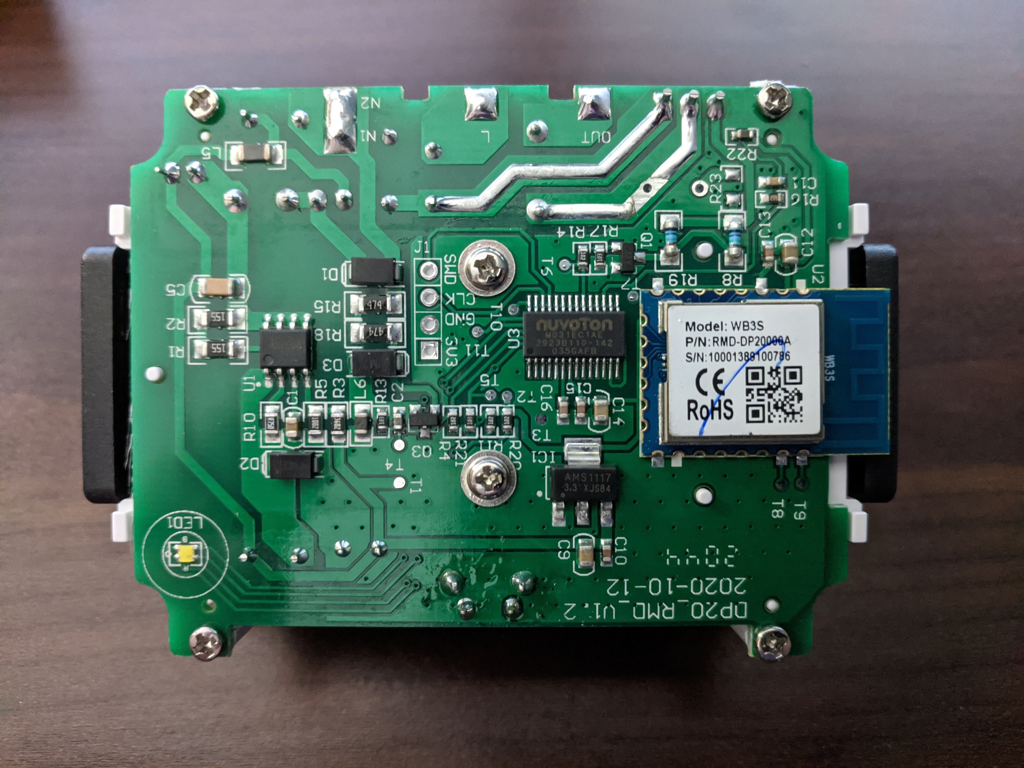
Unfortunately the plug is equipped with a secondary TuyaMCU (Nuvoton M031EC1AE, pictured to the left of the WB3S). This means the plug will use the Tasmota TuyaMCU module (Module 54) once the WB3S is replaced with an ESP.
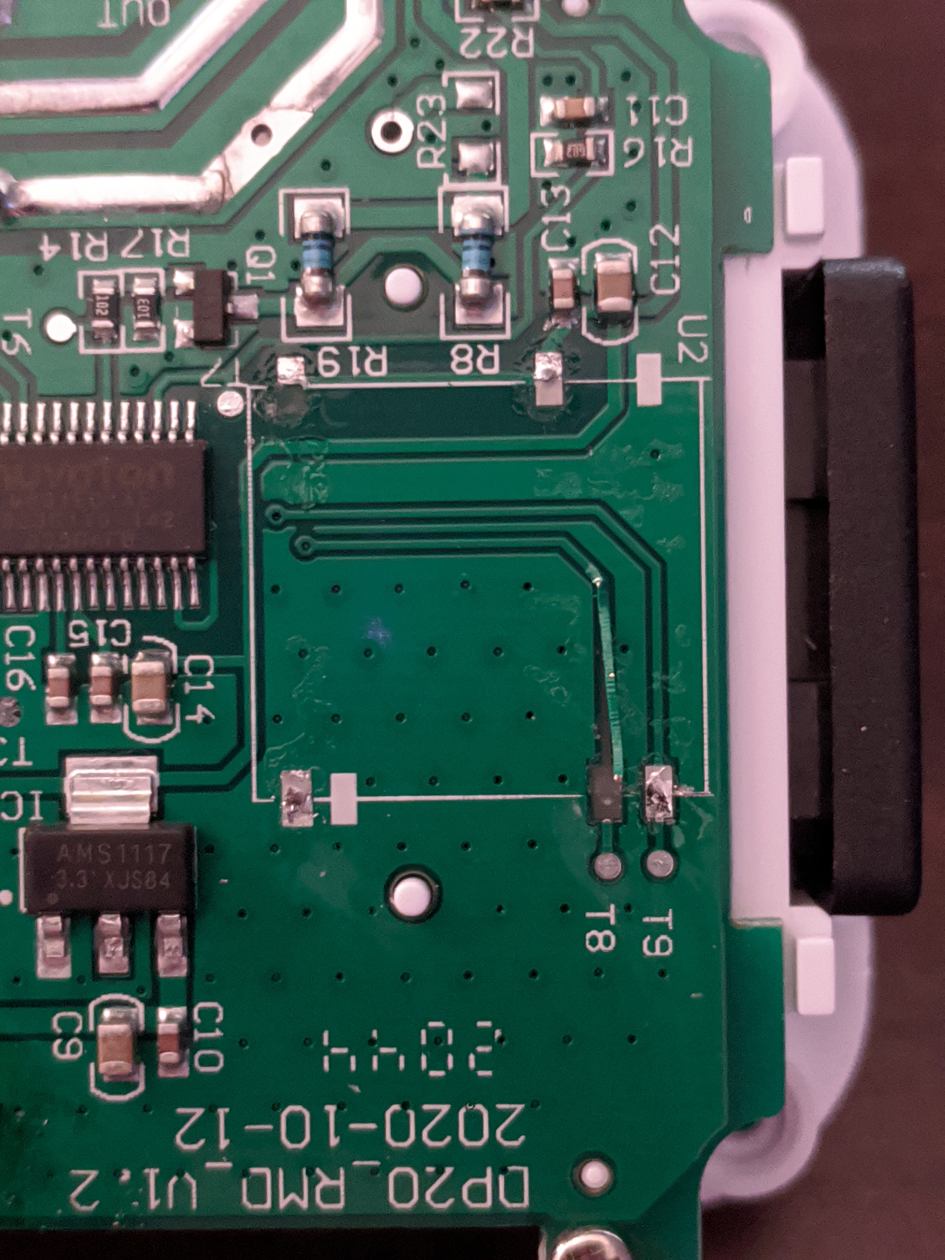
Take care not to remove any of the pads when desoldering the WB3S. I accidentally removed the RX pad on the board when removing the chip (oops). This is a bad situation since this device has a TuyaMCU and relies on a connection between the ESP’s RX TX and the TuyaMCU’s TX RX. If this occurs you can either attempt to repair the connection or solder a wire from RX on the ESP to TX on the Nuvoton MCU. I moved the trace back into its place before soldering the ESP down and miraculously it works, but at some point I might need to open it up to fix it properly.
Picture of the final product with an ESP-12 in place of the WB3S. Note the red wire connecting GPIO15 to GND on the ESP. Without this connection the ESP will not boot to normal mode since there’s no pad on the PCB for GPIO15.
Depending on the light bulbs you use with this device, you might need to modify the DimmerRange command with a different low value. Both outlets are controlled at the same time (no independent control), and the lights gradually fade when turned on or off. Unfortunately it does not fade between brightness levels.
Pinout comparison (WB3S on the left, ESP-12 on the right):
Thank you for this. I swapped out the WB3S for a preloaded tasmota ESP-12 and it worked great. It took a long time to desolder, but it came off eventually. I put in a 10k SMD resistor between the GND and GPIO15 pins.
Works great, cant wait to fix other WB3S things I have laying around.
Thanks for posting this, I thought I was loosing my mind, I put an ESP-12F in place of the WB3S and it just didn’t do anything, removed it and it powered up just fine in the programmer. So I traced down the pins and noticed that GPIO15 and GPIO0 weren’t connected. Your post provided a MUCH needed sanity check for what I was assuming was the problem. Booted and in Tasmota now, thanks!!!
So if you are like me and end up here after banging your head against the wall figuring out why Tasmotizer is not getting any response from the ESP-12F, Mark above me is absolutely right : you need both GPIO0 and GPIO15 connected to GND for this to work (for some reason I read it wrong and only tried one at a time ). After flashing, you can disconnect GPIO0.
As an additional support, here’s the wiring needed for flashing the ESP-12F (notice it’s TX->RX & RX->TX) :
This post is from December 2020 which is well before when LibreTuya came out, but yes, that is definitely a good alternative now. Serial flashing should be easy on this device if cloudcutter doesn’t work.
Just a note in case anyone is playing with these currently: I found that a recently bought Treatlife dimmer plug (mfg 6/2023) requires “Setoption97 1;” because on this unit at least, the Tuya MCU operates at 115200 bps instead of the default 9600 bps.
This is different from the tasmota default.
Aside from that change, this still works perfectly with the onboard WB3S (actually marked CB3S) replaced with a generic ESP12 module flashed with Tasmota.
Furthermore you can build an esphome image for it too using the same config as the in-wall single-pole dimmer https://devices.esphome.io/devices/TreatLife-DS02S and flash it by serial, ota, or through tasmota.
Hardware transplant sounds wasteful as the chip seems to be supported by esphome and cloudcutter should be able to install it over the air. Not even opening the device seems actually necessary.
Cloudcutter wasn’t able to work with this module when I tried it, but that may well be my fault. Regardless, ESP12 modules cost almost nothing and since I was already set up for hot air rework it was a trivial 10 minute job, so I took the easy path.


 ). After flashing, you can disconnect GPIO0.